
ROAD MARKINGS
CHAPTER 7
August 2019

August 2019 7/2
Traffic Signs Manual
Chapter 7 – Road Markings
Contents
Page
7.1 Introduction ..................................................................................................................................6
General ...........................................................................................................................................6
The Function Of Road Markings ....................................................................................................6
Classes Of Marking ........................................................................................................................7
Speed .............................................................................................................................................8
Legal ...............................................................................................................................................8
Materials .........................................................................................................................................8
7.2 Transverse Markings ...................................................................................................................9
Stop Line (RRM 017)......................................................................................................................9
Tram Stop Line (RRM 031) ......................................................................................................... 11
Yield Line (RRM 018) .................................................................................................................. 11
No Entry Line (RRM 019) ............................................................................................................ 12
7.3 Longitudinal Markings .............................................................................................................. 15
Centre Line Markings .................................................................................................................. 15
Climbing / Overtaking Lanes ....................................................................................................... 23
Right-Turn Lanes ......................................................................................................................... 25
Passing Lanes On Type 3 Dual Carriageways ........................................................................... 25
Lane Lines (RRM 003) ................................................................................................................ 26
Merge/Diverge Lane Line (RRM 028) ......................................................................................... 27
Edge Of Carriageway Lines (RRM 025, RRM 026 & RRM 027)................................................. 27
Raised Profile Edge Markings ..................................................................................................... 29
7.4 Hatched Markings
..................................................................................................................... 33
Motorways And High-Quality Dual Carriageways ....................................................................... 34
Other Roads ................................................................................................................................ 36
7.5 Worded And Diagrammatic Markings ..................................................................................... 41
Stop (M 114) ................................................................................................................................ 41
Triangular Yield Marking (M 115) ................................................................................................ 41
Slow (M 106) ............................................................................................................................... 42
Look Left/Right (M 107l/R) .......................................................................................................... 42
Arrows ......................................................................................................................................... 43

August 2019 7/3
Lane Destination Markings (M 105) ............................................................................................ 47
School Keep Clear Marking (RRM 010) ...................................................................................... 49
School Warden Crossing Patrol Point (M 121) ........................................................................... 50
Speed Markings (M 108) ............................................................................................................. 51
Emergency Telephone And Chainage Markings (M 120) ........................................................... 52
7.6 Parking Restrictions And Parking Bays ................................................................................. 53
Parking Restrictions .................................................................................................................... 53
Parking Bays ............................................................................................................................... 54
Taxi Stand (RRM 029)................................................................................................................. 56
Loading Bay (RRM 009) .............................................................................................................. 57
Electric Vehicle Recharging Bay (RRM 034) .............................................................................. 57
7.7 Bus And Tram Markings ........................................................................................................... 58
Bus Stop (RRM 030) ................................................................................................................... 58
Bus Lanes ................................................................................................................................... 60
Tram Lanes ................................................................................................................................. 65
7.8 Cycle Tracks .............................................................................................................................. 67
With-Flow Cycle Tracks............................................................................................................... 67
Contra-Flow Cycle Tracks ........................................................................................................... 69
Cycle Tracks Not On The Carriageway....................................................................................... 69
7.9 Yellow Box Markings ................................................................................................................ 71
7.10 Reflecting Road Studs .............................................................................................................. 73
7.11 Priority Junctions ...................................................................................................................... 76
Ghost Island Junctions ................................................................................................................ 80
Right-Turn Junctions On Dual Carriageways .............................................................................. 80
7.12 Signal Controlled Junctions .................................................................................................... 84
7.13 Roundabouts ............................................................................................................................. 86
Normal Roundabouts .................................................................................................................. 86
Mini-Roundabouts (RRM 033) .................................................................................................... 91
7.14 Grade-Separated Junctions ..................................................................................................... 93
7.15 Level Crossings ......................................................................................................................... 94

August 2019 7/4
7.16 Pedestrian Crossings ............................................................................................................... 96
Zebra Crossing (RPC 001) .......................................................................................................... 96
Signalised Pedestrian Crossing .................................................................................................. 97
Zig-Zag Markings (RPC 002) ...................................................................................................... 98
7.17 Traffic Calming ........................................................................................................................ 102
7.18 Yellow Bar Markings ............................................................................................................... 103
Appendix 7a: Lettering For Worded Markings ............................................................................... 106
Appendix 7b: Airport, Ferry And Disabled Persons Symbols ...................................................... 112
Appendix 7c: Schedule Of Road Markings ..................................................................................... 113

August 2019 7/5

August 2019 7/6
7.1 Introduction
GENERAL
7.1.1 This Chapter provides details of the road markings which may be
used on roads in Ireland, including their layout and symbols, the
circumstances in which each marking may be used and guidance
on positioning them. The chapter should be read in conjunction
with other relevant chapters. Further information on the use of the
Manual is given in Chapter 1.
7.1.2 For the purposes of this Manual:
• Shall or must indicates that a particular requirement is
mandatory;
• Should indicates a recommendation; and
• May indicates an option.
7.1.3 The diagrams for each marking indicate any variants which are
permitted. The standard dimensions for markings are given on the
diagrams or in the relevant tables in this chapter.
7.1.4 Most road markings are regulatory markings which are referred to
in the relevant legislation (see Chapter 1). Regulatory road
markings have numbers which are prefaced by RRM and RPC.
Markings which are non-regulatory have numbers prefaced by the
letter M. Where variations are allowed (such as in the case of
centre line markings) suffix codes have been provided to assist
designers and contractors to identify the variants. It should be
noted that the suffixes do not form part of the legal descriptions of
the markings.
7.1.5 It should be noted that markings conforming to the previous
designs will continue to have legal effect. However, all new or
reapplied markings should conform to the new designs.
7.1.6 Certain regulatory markings (such as Stop and Yield Lines and
those relating to parking restrictions) are associated with
regulatory signs. The latter are described in Chapter 5.
THE FUNCTION OF ROAD MARKINGS
7.1.7 Road markings may be defined as markings on the surface of the
road for the control, warning, guidance or information of road
users. They may be used to supplement upright signs, or they
may be used alone.

August 2019 7/7
7.1.8 Road markings have the limitation that they may be obscured by
snow, leaves or debris on the carriageway. Their conspicuity is
impaired when wet or dirty and their durability depends largely on
their exposure to traffic wear. Nevertheless, they serve a very
important function in conveying information and requirements to
drivers which might not otherwise be possible by the use of upright
signs. They have the advantage that they can often be seen when
an upright sign is obscured, and, unlike such signs, they can
provide a continuing message to the moving driver and, as such,
worded markings must be laid as words would typically be read,
i.e. from top to bottom.
For example;
STAY IN LANE would be laid on the carriageway as follows;
STAY LANE
IN and not as IN
LANE STAY
7.1.9 The continued increase in the volume of traffic using the roads
makes the extensive use of road markings essential to ensure that
full advantage is taken of the available road space. In particular,
widespread use of lane markings is desirable. Enhancing lane
discipline adds to the safety of traffic, besides improving traffic
flows.
7.1.10 Road markings should be considered in detail at design stage in
respect of new or improved roads and junctions. The markings for
existing roads are best considered on plan before the work is
undertaken.
CLASSES OF MARKING
7.1.11 Road markings may be classified as follows:
a. Transverse markings, which are at right-angles (or
thereabouts) to the centre line of the carriageway;
b. Longitudinal markings (including double line systems);
c. Hatched markings;
d. Worded and diagrammatic markings;
e. Markings indicating parking and loading requirements;
f. Bus and tram markings;
g. Cycle track markings;
h. Yellow box markings; and
i. Road studs.
7.1.12 The various classifications are covered in this chapter in the above
order in Sections 7.2 to 7.10. Sections 7.11 to 7.16 illustrate their
application in specific circumstances. Markings used for traffic
calming purposes are included in Section 7.17, and Section 7.18
describes the use of transverse yellow bar markings.

August 2019 7/8
SPEED
7.1.13 Throughout this Chapter reference is made to the ‘speed’ of traffic,
for example to determine the appropriate dimension of line
marking to be used, or to define the visibility requirements for a
continuous line system. Wherever ‘speed’ is mentioned, it shall be
determined as follows:
• On new or improved roads, ‘speed’ is the Design Speed,
calculated in accordance with Transport Infrastructure
Ireland Standard
DN-GEO-03031
1
;
• In the case of existing roads, ‘speed’ is the speed limit,
except when there is a significant difference between the
speed limit and actual vehicle speeds, in which case:
• ‘speed’ shall be the observed 85th percentile approach
speed of private cars. This is the speed which is exceeded
by only 15% of cars in dry weather and may be measured
by accepted speed survey methods.
LEGAL
7.1.14 Traffic signs and road markings are provided in accordance with
signs regulations or directions of the Minister of Transport. They
may be laid only by or on behalf of the Road Authority. Markings
with the prefix RRM or RPC are regulatory road markings, and
attention is drawn to the statutory requirement for the Road
Authority to consult with the Commissioner or appropriate
delegated officer in the Garda Síochána where such markings are
being provided. Markings with the M prefix have no regulatory
significance.
7.1.15 Some road markings indicate a legal requirement (for example the
transverse Stop Line, or longitudinal parking restriction markings)
and may be accompanied by regulatory signing as specified in
Chapter 5.
MATERIALS
7.1.16 The specifications for road markings, including materials,
equipment and methods of application, are detailed in the
Transport Infrastructure Ireland publication CC-SPW-01200
Specification for Road Works Series 1200 - Traffic Signs and Road
Markings
2
, to which the provision of road markings should
conform.
7.1.17 The colour of road markings shall be white, unless otherwise
stated in the Manual.
1
Transport Infrastructure Ireland. DN-GEO-03031, Road Link Design (formerly
NRA TD 9)
. Part of the TII Design Manual for Roads and Bridges. TII, Dublin.
2
Transport Infrastructure Ireland. CC-SPW-01200, Specification for Road Works
- Series 1200 - Traffic Signs and Road Markings. Part of the TII Specification for
Road Works. TII, Dublin.

August 2019 7/9
7.2 Transverse Markings
7.2.1 The prescribed transverse markings comprise:
• Stop Line;
• Tram Stop Line;
• Yield Line; and
• No Entry Line.
STOP LINE (RRM 017)
7.2.2 A 200mm wide Stop Line, RRM 017 indicates the position in
advance of which a vehicle must be brought to a complete halt. At
signals for level crossings or for swing or lifting bridges, the Stop
Line shall be 300mm wide (see Section 7.15).
RRM 017 – Stop Line
† Note: A special width of 300mm shall be used for Stop Lines at
level crossings and swing or lifting bridges.
Junction Stop Line
7.2.3 The marking consists of a single continuous line 200mm in width
(RRM 017) and should be supplemented by a Stop Sign (RUS 027,
see Chapter 5). Where a road joins a national road, a Stop Line
and Sign should normally be used. Section 7.11 gives examples
of the use of the Stop Line and associated road markings at priority
junctions.
7.2.4 The edge of the Stop Line nearest to the major road should not be
closer than 600mm to the line of the back of the paved area of the
major road. Only in limited circumstances should it be sited
elsewhere and then it must be sited so as to halt a driver where
visibility is best.
7.2.5 On a two-way road the Stop Line should always be accompanied
by a Continuous Centre Line, RRM 001, extending longitudinally
back from the junction. In normal circumstances this should
extend for 20m from the Stop Line, but this may be reduced to a
minimum of 8m as site conditions require. On roads less than
5.3m width only, the centre line marking may be reduced to 2m.
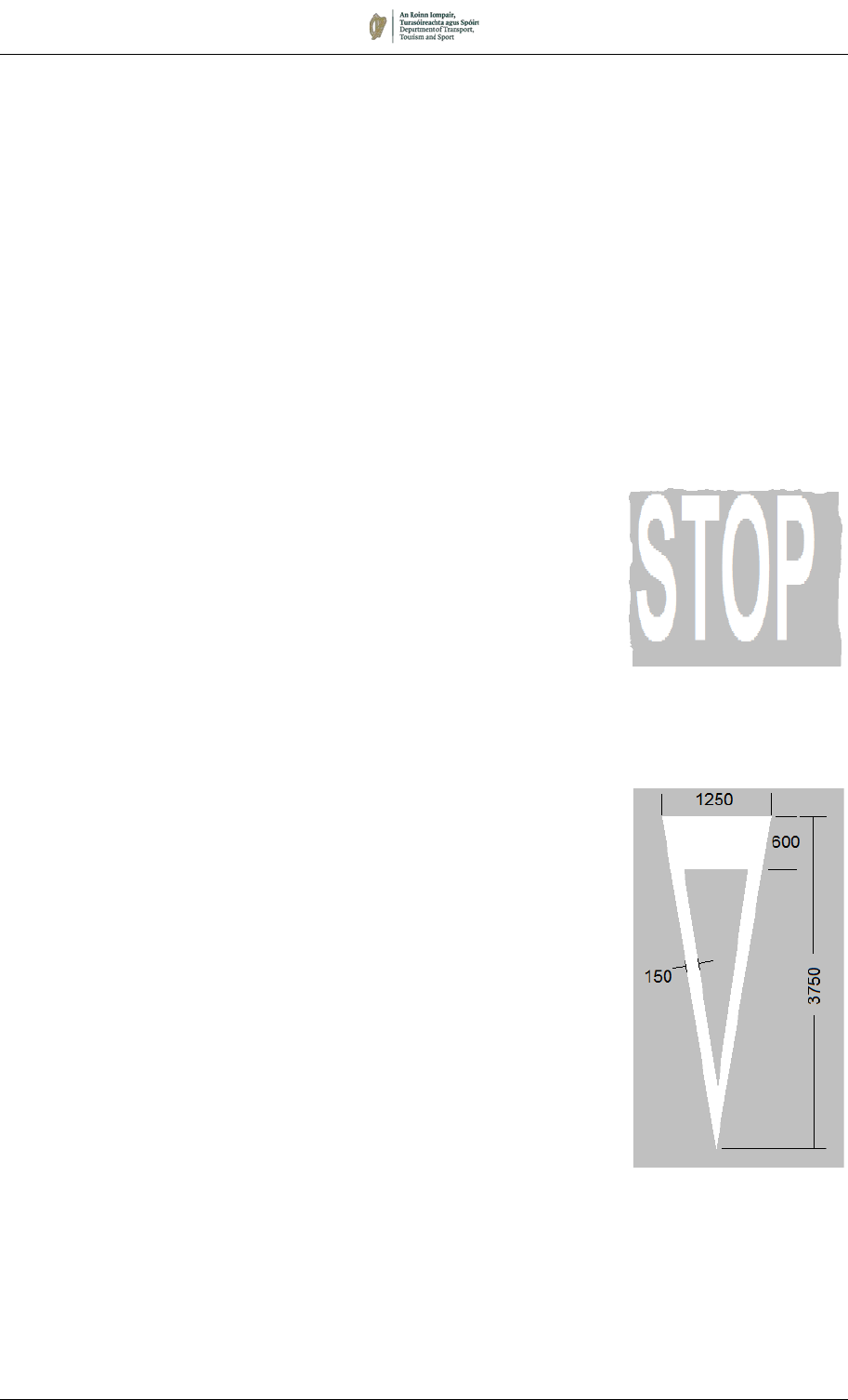
7.2.6 The STOP worded marking, M 114, may be used to increase
conspicuity, as described in Section 7.5. Where used it should
have letters of height either 1600mm or 2800mm; the larger size
is recommended for use on high-speed approaches.
August 2019 7/10
Traffic Signal Stop Line
7.2.7 At traffic signals the Stop Line is a single continuous line 200mm
in width (RRM 017). At signals for level crossings or swing or lifting
bridges the line is 300mm wide.
7.2.8 At traffic signals, including pedestrian signals, the Stop Line is
normally located 1m to 2m before the nearside primary signal, but
site conditions may necessitate variations to this distance. Section
7.12 gives examples of the use of the Stop Line at signal-controlled
junctions, Section 7.15 at level crossings and Section 7.16 at
pedestrian crossings. See also Chapter 9.
Figure 7.1: Stop Line at Signalled Controlled junction
Advance Cycle STOP Lines
7.2.9 Where there is a need to assist cyclists in establishing their
position in advance of other traffic at a signal-controlled Stop Line
(for example, to facilitate safer right-turn manoeuvres), an
Advanced Stop Line may be provided. They shall not be used at
level crossings or standalone signal-controlled crossings for
pedestrians, cyclists or equestrians.
7.2.10 Vehicles other than cycles must stop at the first line when signalled
to do so. A cycle track must be provided to enable cyclists to enter
the reservoir lawfully: i.e. without crossing the first Stop Line. The
area between stop lines across the full width of the approach is
available for cyclists to wait at the red light. This area and the
approach lane may be highlighted using coloured surfacing. Both
Stop Lines shall be 200mm wide.
7.2.11 For guidance on the design and layout of cycle facilities refer to
Department of Transport
guidelines for cycling facilities.

August 2019 7/11
TRAM STOP LINE (RRM 031)
7.2.12 The Tram Stop Line, RRM 031, indicates the point beyond which
a light rail vehicle shall not proceed when stopping in compliance
with the appropriate regulatory sign or traffic signal (see Chapters
5 and 9).
RRM 031 – Tram Stop Line
YIELD LINE (RRM 018)
7.2.13 The Yield Line marking, RRM 018, imposes a requirement on all
approaching traffic to yield to conflicting traffic. The edge of the
transverse line nearest to the major road should not be closer than
600mm to the line of the back of the paved area of the major road.
RRM 018 – YIELD Line
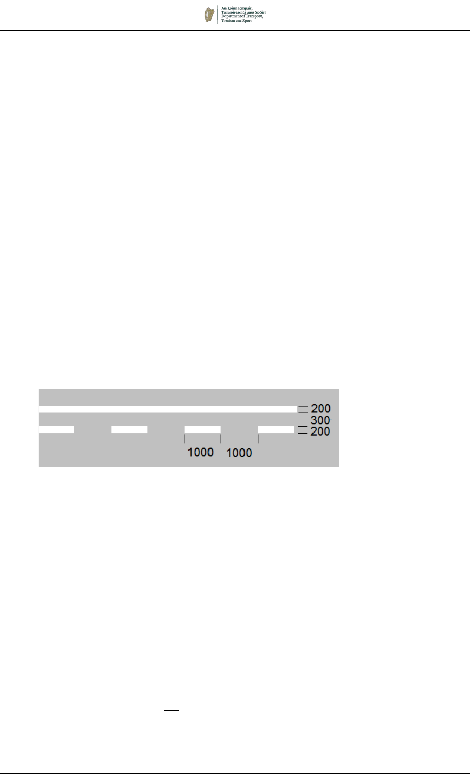
7.2.14 The marking generally consists of a 200mm wide broken line
comprising 1000mm marks and 1000mm gaps. Where the width
of the approach lane is not sufficient to display this pattern,
segments of 500mm marks and 500mm gaps may be used
instead. This dimension is also used at Zebra pedestrian
crossings, where it forms part of marking RPC 001 (see Section
7.16). The 100mm wide, 300mm segment and gap is reserved for
cycle track yield lines, where it is designated as marking RRM
018C (see Section 7.8).
7.2.15 The Yield Line should normally be supplemented by the Yield Sign
(RUS 026, see Chapter 5) at priority-controlled junctions. On
national roads the Yield Sign must always accompany the Yield
Line. The Yield Sign is not required to accompany the Cycle Yield
Line, RRM 018C.
7.2.16 On two-way roads, the marking generally extends to the centre of
the carriageway of the minor road. On a one-way road it is carried
August 2019 7/12
across the whole width of the minor road. The precise location of
the marking nearest to the major road in relation to the edge of the
major road is governed by the same considerations as pertain to
the Stop Line. At junctions, the Yield Line is normally
accompanied by one or more Triangular Yield Markings, M 115
(see Sections 7.5 and 7.11).
7.2.17 On two-way roads, the Yield Line should be accompanied by a
Continuous Centre Line, RRM 001, extending longitudinally back
from the junction for a minimum distance of 20m from the Yield
Line but this may be reduced to a minimum of 8m as site conditions
require. On roads less than 5.3m width only, the centre line
marking may be reduced to 2m.
7.2.18 Section 7.11 gives examples of the use of the Yield Line at priority
junctions.
NO ENTRY LINE (RRM 019)
7.2.19 The No Entry Line, RRM 019, indicates to drivers the point beyond
which entry is prohibited. It also indicates the position at which a
driver emerging from a one-way street must yield to conflicting
traffic. The marking consists of one continuous line and one
broken line comprising 1000mm marks and 1000mm gaps. The
lines are 200mm wide and are spaced 300mm apart. It should be
accompanied by No Entry and either Stop or Yield Signs. Its use
is illustrated in Section 7.11.
RRM 019 – No Entry Line
Priority Junctions
7.2.20 The marking shall extend across the entire width of a one-way
road. The precise location of the continuous marking nearest to
the major road is governed by the same considerations as the Stop
Line.
7.2.21 The No Entry Line must be accompanied by the regulatory signs
defined in Chapter 5: i.e. No Entry Signs (RUS 050) on both sides
of a one-way road at its junction with an intersecting road and No
Left Turn and No Right Turn Signs (RUS 013 and RUS 012) on the
approaches to the junction on the intersecting road.
7.2.22 The No Entry Line shall not be used at locations where an
exemption to the No Entry Sign exists: i.e. where the No Straight
Ahead Sign (RUS 011) is used with exemption plates (see Chapter
5).

August 2019 7/13
Roundabouts
7.2.23 The No Entry Line is also used at the entry arms of roundabouts,
to indicate the location at which traffic approaching the roundabout
shall yield to traffic on the circulating carriageway. This is
illustrated in greater detail in Section 7.13, and in Chapter 10.
7.2.24 When used at roundabouts, they shall be supplemented by Yield
(RUS 026) and/or Mini-roundabout (RUS 049) upright signs as
described in Chapter 5, and may also be accompanied by Yield
triangle markings, M 115, in each approach lane. Depending upon
site conditions, No Entry signs (RUS 050) may be provided to
prevent circulating traffic from turning the wrong way into an
approach road.
One-Way Systems and Dual Carriageways
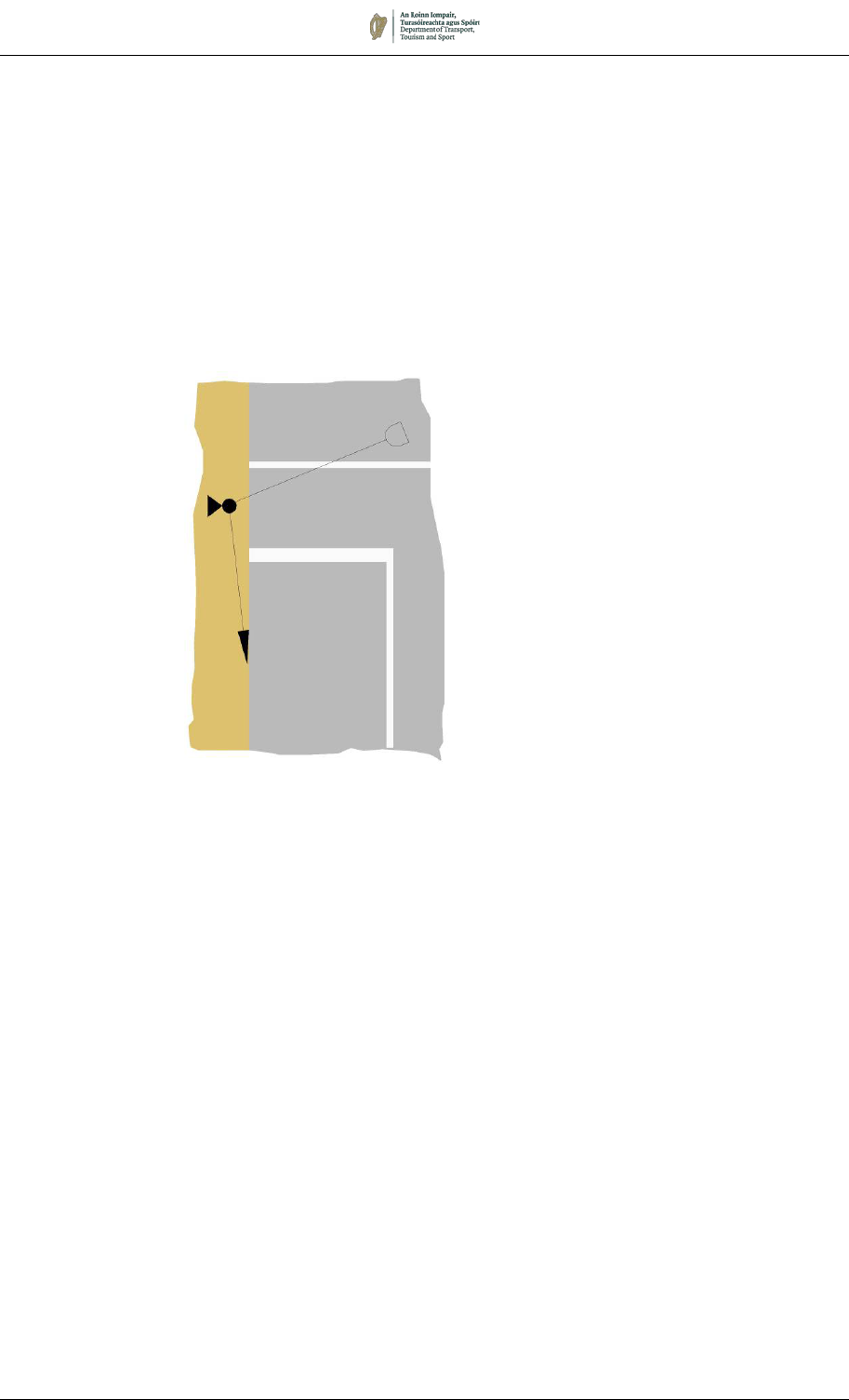
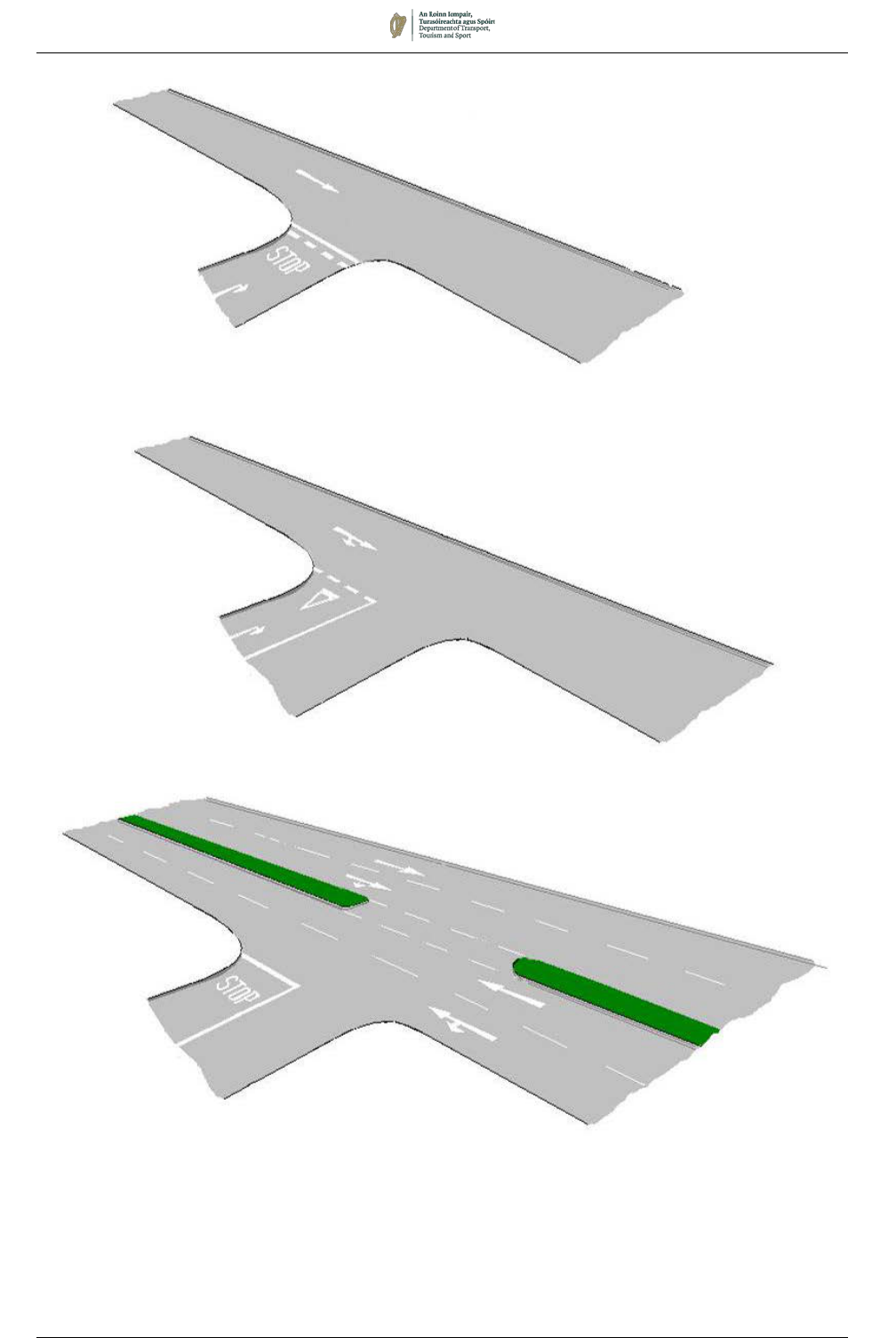
7.2.25 When the major road is one-way or a dual carriageway, Lane
Indication Arrows (as described in Section 7.5) should be used on
the major road instead of No Entry Lines to provide clear
indications of traffic direction to traffic emerging from the minor
road (see Figure 7.2). No Entry signs may still be provided as
appropriate.
August 2019 7/14
(a) Road Markings at the Junction of Two One-Way Roads
(b) Road Markings Where a Two-Way Road Meets a One-Way
(c) Road Markings at a Junction with a Dual Carriageway
Figure 7.2: Markings at Typical Priority Junctions
Note:
See to Chapter 5 for upright sign requirements.
August 2019 7/15
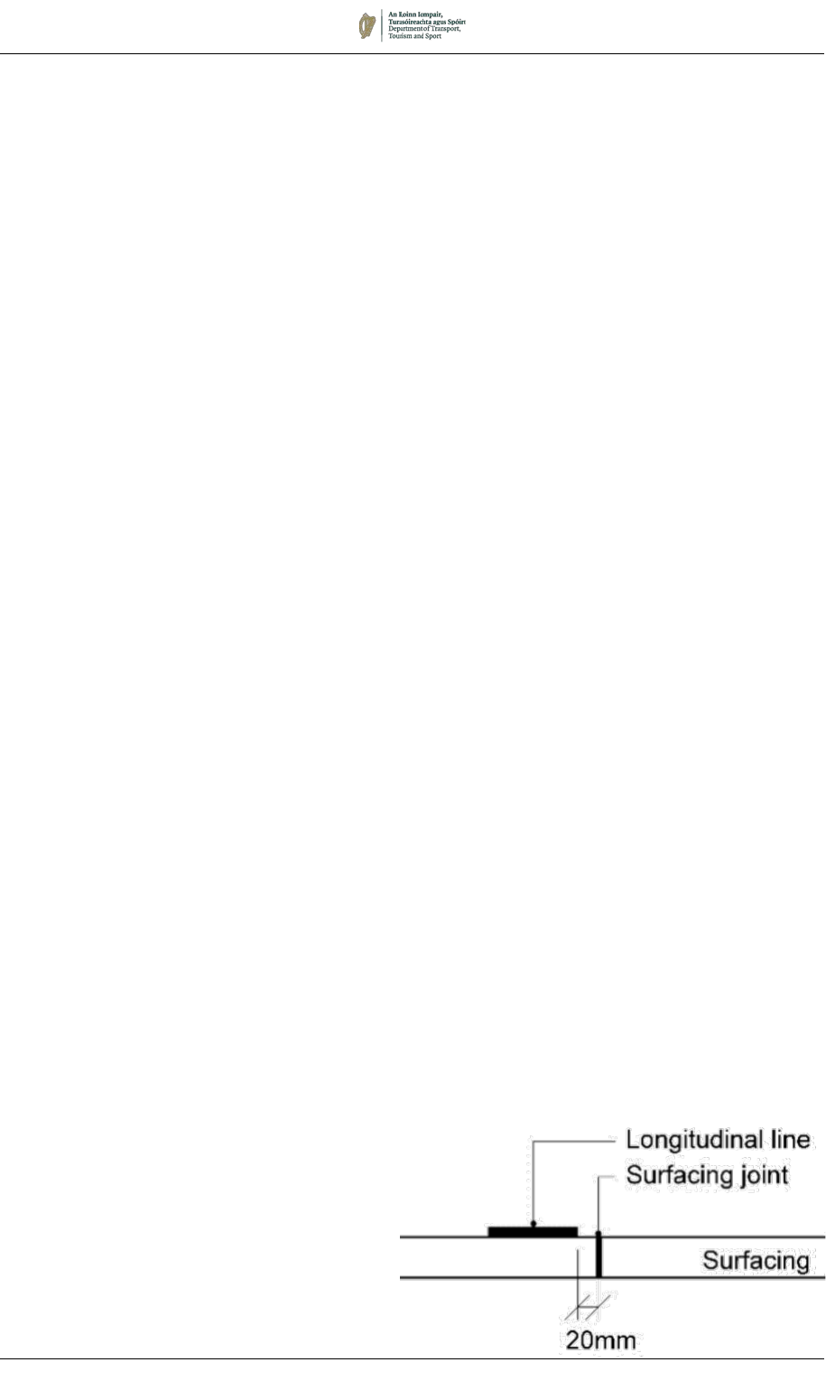
Figure 7.2(a):
Longitudinal Line
Offset from
Surfacing Joint
7.3 Longitudinal Markings
7.3.1 The benefits to be gained from the use of lane, centre and edge of
carriageway lines in both urban and rural areas cannot be
emphasised enough. By guiding and confining traffic to its correct
lane, the lines have an important bearing on safety, besides
ensuring that all the available carriageway space is used to its
maximum capacity.
7.3.2 Drivers need to be able to detect guidance markings at a distance
equivalent to a minimum of two seconds of travel time. If the
visibility is less than this, drivers tend to adjust too late when the
road changes direction. They run too close to the centre line on
left hand bends, or too close to the road edge on right hand bends.
The higher the prevailing traffic speed, the greater the visibility
distance required to maintain this two-second ‘preview’ time. If it
is not provided, drivers tend to miss the curve, or proceed in a
series of staggers.
7.3.3 A variety of factors influence the visibility distance of road
markings. It is increased when a line is wider, has a higher line-
to-gap ratio or has a higher coefficient of retroreflective luminance.
For the purpose of determining the size of marking to be used,
reference should be made to the ‘speed’ of traffic, which should be
determined as described in Section 7.1.
7.3.4 In general, for any given road configuration there will be alternative
dimensions prescribed for centre, lane and edge lines: one for
traffic speeds of 60km/h or less (predominantly urban areas), the
other for speeds greater than 60km/h (predominantly rural areas).
Special cases such as motorways are noted in the relevant
sections.
7.3.5 Where the traffic speed (for the purposes of determining which size
of marking should be used) varies along a route, resulting in a
mixture of marking sizes along that road, judgement should be
exercised to select the more appropriate marking size to adopt for
consistency along its length.
7.3.6 Longitudinal lines should be formed of full multiples of the line
module length; use of segments of line module lengths should be
avoided. Where continuous longitudinal lines are used, it is
permitted to incorporate ‘drainage gaps’ as required to prevent
surface water ponding. These gaps should be no longer than
100mm and may be spaced at intervals of not less than 2m.
7.3.7 Longitudinal lines laid on road pavement joints are not durable. For
that reason, when roads are being surfaced, longitudinal joints in
surfacing should be offset from the locations at which centre, edge
and lane lines are to be placed, as shown in Fig 7.2(a) Longitudinal
Line Offset from Surfacing Joint

August 2019 7/16
RRM 001:
Continuous Single
Centre Line
CENTRE LINE MARKINGS
7.3.8 The centre line markings described in this Section should be used
on single-carriageway roads to separate traffic travelling in
opposite directions.
7.3.9 A centre line marking (and the centre of a Double Line system) is
usually positioned on the geometric centre of the carriageway;
however, they may be laid off-centre in certain situations, such as
where parking is provided along one side, and on roads with an
additional lane in one direction (e.g. a bus, cycle or climbing lane).
7.3.10 The visibility distances used in selecting the appropriate type of
centre line marking are stated in Table 7.3. It should be noted that
for short interruptions to visibility it does not automatically follow
that a more restrictive centre line type must be used. Judgement
should be used but, in general, a short obstruction to visibility
occurring over a distance of no more than one third of the length
W-S in Table 7.3(a) may be disregarded.
7.3.11 The minimum length of a stretch of centre line marking of any one
type should be W - S in Table 7.3(a), except where otherwise
stated in this Chapter (see 7.3.18 iii for example)
7.3.12 On roads of 6.0m or more in width, centre line markings should be
provided. Broken Centre Lines, RRM 002A or B, may be provided
where forward visibility is considered adequate for drivers to
observe and react to oncoming vehicles. Where forward visibility
is limited, for example on bends, humps or dips, the centre line
markings should be Warning Lines, RRM 002C or D, or
Continuous Lines RRM 001, as appropriate.
7.3.13 Centre line markings on two-lane roads on which the speed is
80km/h or less should generally be 100mm wide. On roads with a
speed in excess of 80km/h 150mm wide centre line markings
should generally be used; however, for rural roads of national
classification, centre line markings should generally be 150mm
wide, regardless of the speed. It is important that Lane Lines, RRM
003, which separate traffic travelling in the same direction, should
not be mistaken by drivers for centre line markings, which separate
traffic travelling in opposite directions. Consequently, on multi-lane
roads a 150mm wide centre line marking should be used.
Narrow Roads
7.3.14 On narrow roads, over-running of the carriageway edge causing
maintenance problems can occur if centre line markings are
provided. Drivers might also expect a road marked with a centre
line to be wide enough for opposing lanes of traffic to pass.
Therefore, on roads less than 5.0m width, centre line markings
should be omitted. For widths between 5.0m and 6.0m, provision
of a centre line marking is optional. In general, well-aligned roads
wider than 5.5m should be provided with a centre line marking;
poorly-aligned roads below 5.5m width should not, and judgement
should be used in intermediate cases. Section 7.3.54 provides
guidance on the use of Edge Lines where provision of a centre line
marking is not feasible.
7.3.15 Use of a Double Line System (as described in 7.3.28) should
generally be avoided on roads less than 6.0m wide
August 2019 7/17
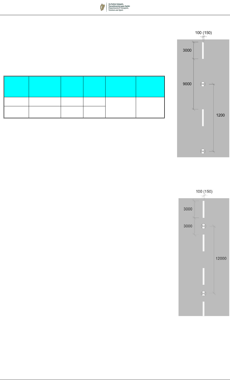
Broken Centre Line (RRM 002A and B)
7.3.16 Two alternative dimensions for Broken Centre Lines are
prescribed. The standard modules (the combination of one
segment and one gap) are 12m (RRM 002A) and 6m (RRM 002B),
and their use is specified in Table 7.1.
Table 7.1: Broken Centre Line RRM 002 A and B
Speed
(km/h)
Marking Line
Length
(mm)
Gap
Length
(mm)
Line
Width
(mm)
Stud
Spacing
(mm)
> 80 RRM 002A 3000 9000 See
paragraph
7.3.13
See
Section
7.10
≤ 80 RRM 002B 3000 3000
7.3.17 In certain circumstances Broken Centre Line, RRM 002A or B
should be replaced by Warning Centre Line, RRM 002C or D (see
following paragraphs), or Continuous Centre Line, RRM 001, or
Double Line System.
12 metre Module
RRM 002A
6 metre Module
RRM 002B
RRM 002:
Broken Centre
Line
August 2019 7/18
Warning Centre Line (RRM 002 C and D)
7.3.18 As described earlier in this Section, the prominence of longitudinal
markings can be enhanced by increasing the line-to-gap ratio.
Where forward visibility is restricted, or on the approach to some
other hazard (e.g. a roundabout or other junction), the centre line
marking may be replaced with Warning Lines (RRM 002C or D).
7.3.19 Warning Centre Lines should be used in the following situations:
i. on bends and crests where forward visibility is restricted to
less than the distance recommended for use of Broken Centre
Line, but still exceeds the visibility criteria for Continuous Line.
Table 7.3 gives the visibility distances S and W (for specific
speed ranges) between which Warning Centre Lines should
normally be provided;
ii. where it is necessary to highlight the presence of a road
junction, central refuge, level crossing or other hazard and
Continuous Lines are not being provided;
iii. at rural junctions where Continuous Line markings are not
being provided. A minimum length of seven marks of Warning
Centre Line should be provided on each major road approach;
and
iv. on the approach to a Continuous Line to give advance
warning.
For cases i, ii and iv above, the minimum length of Warning Centre
Line should be W - S stated in Table 7.3(a).
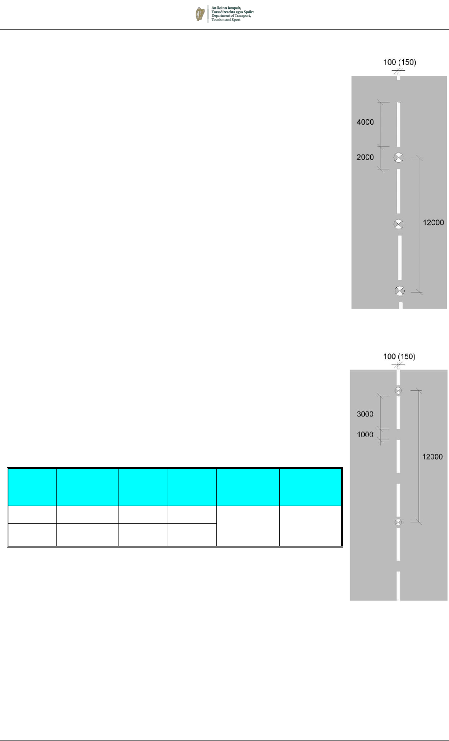
7.3.20 Two patterns of Warning Line are prescribed. The standard
modules (the combination of one segment and one gap) are 6m
(RRM 002C) and 4m (RRM 002D), and their use is specified in
Table 7.2.
Table 7.2: Size of Centre Line Warning Marking RRM 002 C and D
Speed
(km/h)
Marking Line
Length
(mm)
Gap
Length
(mm)
Line Width
(mm)
Stud
Spacing
(mm)
> 80 RRM 002C 4000 2000
See
paragraph
7.3.13
See
Section
7.10
≤ 80 RRM 002D 3000 1000
7.3.21 Overuse of the marking should be avoided. Its use where not
justified will devalue its effect. Particular care should be taken in
urban areas where there might be a temptation to use it
extensively.
4 metre Module
RRM 002D
RRM 002:
Warning Centre
Line
6 metre Module
RRM 002C

August 2019 7/19
Continuous Centre Line (RRM 001)
7.3.23 Where crossing of the centre line is to be prohibited, the
longitudinal marking should be a Continuous Centre Line (RRM
001). Where the visibility distance is less than the value of S (Table
7.3), use of a Continuous Centre Line should be considered.
However, see 7.3.14 for guidance on narrow roads below 6.0m
width.
7.3.24 It should be noted that where the visibility standards are not
satisfied, it does not automatically follow that continuous lines
must be laid down. Judgement should be exercised in deciding
whether, having regard to the width, alignment and traffic
characteristics of the route, it is reasonable to impose the
restrictions or whether Warning Centre Line should be used
instead. Use of Warning Centre Line instead of Continuous Line
may be considered on narrow or poorly aligned roads that are low
speed, low volume, or carry significant volumes of slow-moving
traffic (such as agricultural vehicles, cyclists and pedestrians). The
wide variability in driving conditions on such roads is often not
adequately catered for by precise marking of overtaking and non-
overtaking sections. Provision of a Warning Centre Line may
sometimes be preferable, allowing the driver flexibility to decide
whether or not the prevailing traffic conditions permit safe crossing
of the centreline.
7.3.25 Continuous Centre Line should be provided on the approach to a
hazard located on the centre of the road, such as a physical island,
a bollard or a ghost island sheltering a right-turn lane. The length
should be no shorter than W - S stated in Table 7.3(a) and, in the
case of a ghost island right-turn lane, the length should normally
be measured to the direct taper of the right-turn lane (not to the
commencement of the hatching).
7.3.26 It should be noted that drivers may cross a Continuous Line
(whether a single line RRM 001 or one that is part of a Double Line
System) to enter or leave land or premises on the right-hand side
of the road. It is not necessary, therefore, to break the line at such
locations. However, a Continuous Line should generally be broken
across a junction by provision of five marks of RRM 003C line.
7.3.27 Overuse of the Continuous Centre Line marking should be
avoided.
It is important that it is not used where the appropriate
criteria are not satisfied, otherwise it will lose the respect of drivers
.
In urban areas the centre line of the road is frequently crossed by
drivers and, for that reason, a Continuous Centrelines should not
generally be used in urban areas.
Roundabouts
7.3.28 A Single Continuous Line, RRM 001, should also be provided
adjacent to the central island of a roundabout (see Section 7.13).
August 2019 7/20
Double Line System
7.3.29 The Double Line System consists of two lines separated by a gap.
Any of the three types of centre line markings (Broken, Warning or
Continuous), may be used together to form a Double Line System.
It permits each direction of travel to be separately marked
according to the visibility available and is for use on rural roads of
sufficient width (see 7.3.15) on which the visibility would warrant a
different centre line marking in each direction of travel. The
standard of visibility justifying the lengths of lines is strictly
governed by the speeds of vehicles on the road. Table 7.3 sets
out the visibility criteria for various speed ranges. Figure 7.2(b)
shows examples of Double Line Systems and in the case of a
system composed of two broken lines, the markings of the
constituent lines should be co-ordinated as shown.
7.3.30 Sections of Double Line System formed of lines of the same type
should not generally be longer than distance W – S stated in Table
7.3(a).
7.3.31 The width of the gap between lines forming a Double Line System
should be a minimum of 100mm wide but should generally be the
same width as each line comprising the double line system. The
distance between the two markings may be increased to 1200mm
in certain circumstances, accompanied by hatching as described
in 7.3.34 to 7.3.35.
Figure 7.2(b):
Double Line System

August 2019 7/21
Table 7.3: Visibility Requirements
Visibility Distance
(m)
1
Minimum
Line Length
(m)
Speed
(km/h)
S
2
Continuous
Line
W
2
Warning
Line
W – S
3
≤ 50 85
4
145 60
51 – 60 105
4
175 70
61 – 70 125 205 80
71 – 85 145 245 100
> 85 175 290 115
Notes:
1.
Visibility distance is measured from an eye height of 1.05m above
the centre of the carriageway to a target at the same height on the
centre of the carriageway;
2.
The line type indicated in the table is to be provided when visibility is
less than the relevant Visibility Distance;
3.
The distance W - S is to be used as:
a. the minimum length of a Continuous Line, Warning Line or
Broken Line in a direction of travel;
b. the minimum length of a Double Line System;
c. the maximum length of a section of Double Line System formed
of lines of the same type.
4.
Use of Continuous Centre Line within an urban area should be
avoided.
7.3.32 Where a section of road forms a link between two sections of
Continuous Centre Lines and this would result in a length of
Warning Line of less than the length W - S stated in Table 7.3,
Continuous Lines should be provided throughout.
Design of Centre Road Markings
7.3.33 A site visit should always be made when designing road markings,
and designs should not be based solely on plans and longitudinal
sections. During the preliminary marking out it will be possible to
pin-point obstructions to sight lines on bends (e.g. bushes,
hedges, banks, etc.). These should be removed where practicable
and the prohibitory line terminals rechecked before lines are
painted. Marking-out should be done while hedges are in full
foliage. In addition, during the marking out operations special note
should be taken of the existence of bus stops or other facilities
which would tend to cause vehicles to stop on sections of road with
continuous white lines. Between marking out and commencement
date, every effort should be made to have them relocated outside
the section.
7.3.34 The visibility distances used in the design should be based on the
traffic speeds as set out in Section 7.1.
Table 7.3(a): Line Length
August 2019 7/22
Bends and Crests
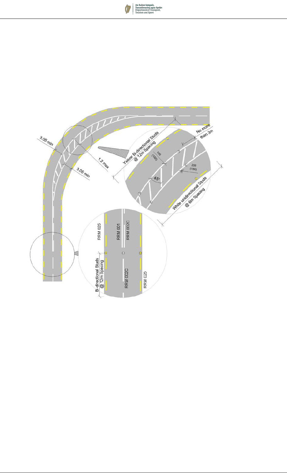
7.3.35 On sharp bends where a Double Line System is to be provided,
the lines can be splayed to form a type of central ‘ghost’ island with
a maximum overall outside width of 1.2m, provided there is ample
room on either side to enable vehicles to negotiate the bend. The
area between the lines must be hatched with inclined 200mm wide
lines generally at 2.0m spacings but no greater than 3.0m spacings
(M 104): see Figure 7
.3. Abrupt changes to lane alignment, resulting
from too sharp a taper rate, should be avoided.
7.3.36 A crest may be treated in a similar way as a horizontal bend.
Where a Double Line System is to be provided, the lines may be
opened out at an inclination not exceeding 1 in 50 as they
approach the point of minimum visibility (often not the highest
point) to attain a maximum overall outside width of 1.2m.
Figure 7.3: Hatching on Bend within Double Line System (M 104)

August 2019 7/23
Exceptional Use of Double Centre Lines
7.3.37 In exceptional circumstances, with the consent of the Overseeing
Organisation, the Double Line System may be used even though
the visibility conditions in both directions are better than the
relevant distances in Table 7.3. Such circumstances might include
markings carried out in conjunction with traffic calming measures,
or to separate opposing traffic flows on three or four-lane single
carriageway roads.
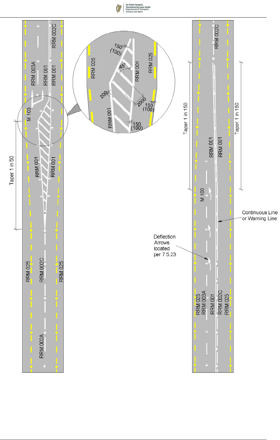
CLIMBING / OVERTAKING LANES
7.3.38 Where a climbing lane is provided on a single carriageway road,
the three-lane climbing / overtaking section should be marked with
a Lane Line, RRM 003 (100mm wide), separating the two uphill
lanes and a Double Line System separating the uphill lanes from
the downhill lane. The Double Line System should feature a
Continuous Line, RRM 001, for uphill traffic in all cases, and either
a Continuous Line or a Warning Line for downhill traffic, depending
on visibility. A Broken Line, RRM 002A or RRM 002B, should not
be used for downhill traffic.
7.3.39 To avoid frequent changes of pattern on long hills, or for safety
reasons, the designer may use a downhill Continuous Line even
where the visibility criterion for a Warning Line is satisfied.
However, the use of a prohibitory line on long, straight sections
should be avoided if possible.
7.3.40 The markings at the start of the climbing lane should be designed
to encourage uphill drivers to keep to the left-hand lane unless
overtaking.
7.3.41 The hatched area preceding the commencement of a climbing
lane shall be formed by Diagonal Hatch markings (RRM 021, see
Section 7.4) bounded on either side by Continuous Lines (RRM
001), as shown in Figure 7.4.
7.3.42 Typical layouts for the markings at the ends of a climbing lane are
indicated in Figures 7.4 and 7.5. For guidance on the provision of
climbing lanes see Transport Infrastructure Ireland Standard DN-
GEO-03031
3
.
3
Transport Infrastructure Ireland. TII DN-GEO-03031, Road Link Design. Part of
the TII Design Manual for Roads and Bridges. TII, Dublin.
M104
Ghost Island at
Crest
August 2019 7/24
Figure 7.4: Longitudinal Lining for a Climbing Lane
Start of
Climbing
Lane
End of
Climbing
Lane
August 2019 7/25
RIGHT-TURN LANES
7.3.43 For guidance on the provision of markings for right turn lanes on
single and dual carriageways, see Section 7.11.
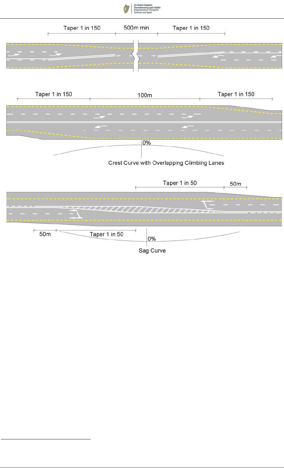
PASSING LANES ON TYPE 3 DUAL CARRIAGEWAYS
7.3.44 For guidance on the provision of markings at the ends of passing
lanes on Type 3 Dual Carriageways, see Transport Infrastructure
Ireland Standard
DN-GEO-03031
4
.
4
Transport Infrastructure Ireland. TII DN-GEO-03031, Road Link Design. Part of
the TII Design Manual for Roads and Bridges. TII, Dublin.
Figure 7.5:
Double Line System Between Two Climbing Lanes on a Crest or Sag
August 2019 7/26
LANE LINES (RRM 003)
7.3.45 Lane Lines, RRM 003, (lane guidance markings) are used to divide
the carriageway into two or more lanes for traffic travelling in the
same direction. Their use can ensure that available carriageway
space is used to its maximum. In helping vehicles to maintain a
consistent lateral position, they also offer safety benefits and
should be used wherever possible.
7.3.46 Two alternative longitudinal dimensions for lane guidance lines are
prescribed. The standard modules (the combination of one
segment and one gap) are 12 metres (RRM 003A) and 4 metres
(RRM 003B). The 12-metre module is the default lane guidance
marking for all roads.
7.3.47 It is important that lane guidance markings, which separate traffic
travelling in the same direction, should not be mistaken by drivers
for centre line markings, which separate traffic travelling in
opposite directions. Consequently, on climbing or passing lanes
on single-carriageway roads the narrower line width should be
used for lane guidance markings, and the wider width for centre
lines. On dual carriageways and motorways, the 100mm Lane
Line width is usually sufficient, but where greater conspicuity is
required (for example where it is important that drivers stay in lane
through an intersection) the 150mm width may be used.
7.3.48 The 4-metre module is used on multi-lane approaches to
signalised and priority junctions, roundabouts, level crossings or
other hazards. A minimum of 5 markings should be provided on
roads subject to a speed limit up to 50km/h, and 7 markings on
roads with a greater speed limit.
7.3.49 The 4-metre module should also be used to delineate the edge of
speed change lanes on the approaches to junctions (for example,
a segregated right-turn lane). On motorways and high-speed dual
carriageways, the edge of a merge or diverge lane shall be
delineated with the 250mm wide Merge/Diverge Lane Line, RRM
028, described on the next page.
7.3.50 In certain situations, it may be necessary to provide Lane Lines
which cross the path of conflicting traffic flows. This situation can
occur for example on the circulating carriageway of a signalled
roundabout or within the controlled area of a signal-controlled
junction. In these instances, RRM 003C as described in Section
7.13 may be used.
12 metre module
RRM 003A
4 metre Module
RRM 003B
RRM 003: Lane Lines
August 2019 7/27
MERGE/DIVERGE LANE LINE (RRM 028)
7.3.51 On motorways and high-speed dual carriageways, the boundary
between a merge or diverge lane and the rest of the carriageway
should be delineated with a Merge/Diverge Lane Line, RRM 028.
This consists of a 250mm wide broken marking with 2m long lines
and 2m gaps. Unidirectional green road studs should be laid at
8m centres along the marking (see Section 7.10).
7.3.52 The Merge/Diverge Lane Line should be marked from the start of
a diverge lane (see Figure 7.7). A bifurcation arrow (M102) should
be provided to highlight the presence of the diverge lane, and a
short gap may be provided in the line and studs to accommodate
the head of the diverge arrow. Chevron markings are normally
required at merges and diverges in addition to Merge/Diverge
Lane Lines (see Sections 7.4 and 7.14). Layouts of the signs and
markings at typical junctions incorporating merges and diverges
are illustrated in Chapter 10.
7.3.53 For extended diverge situations, for example at a diverge lane-
drop, this marking is used to segregate the nearside lane(s) from
the ahead lanes. The marking should commence at the first
Advance Direction Sign (ADS), normally 1km in advance of the
diverge point. However, in the case of an auxiliary merge/diverge,
the marking should span between the merge and diverge points.
Figure 7.7:
Start of Diverge Lane Marking
Diverge Lane Marking discontinued when the gap is
100m max in length or 2.5m from the taper.
RRM 028:
Merge/Diverge
Lane Line
August 2019 7/28
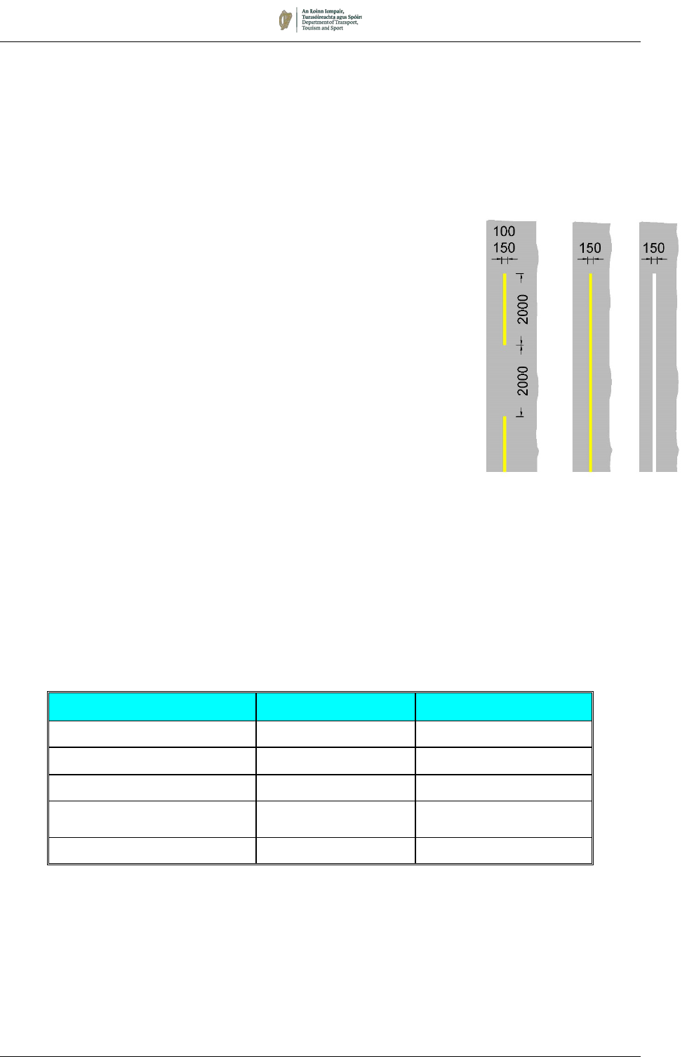
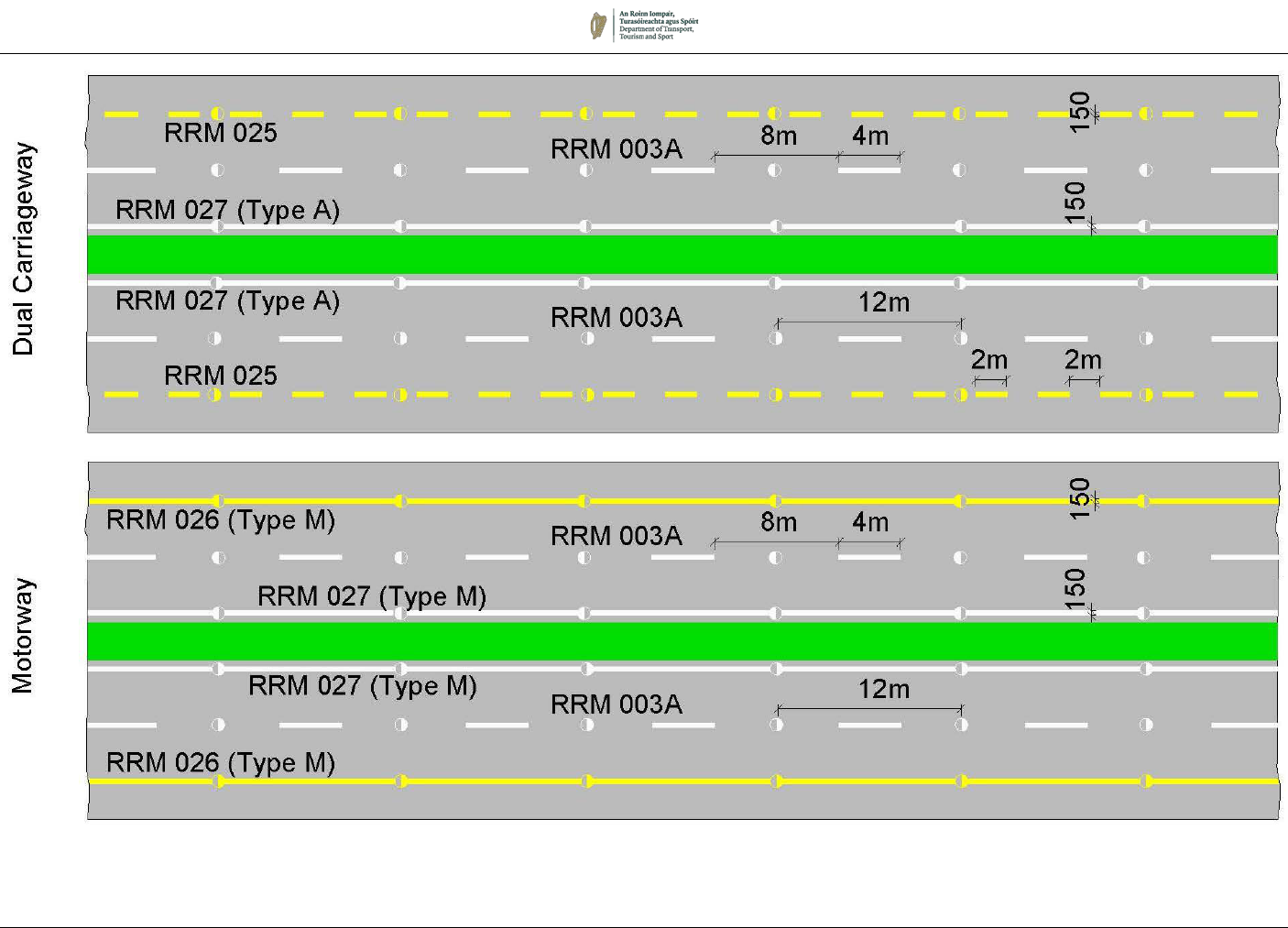
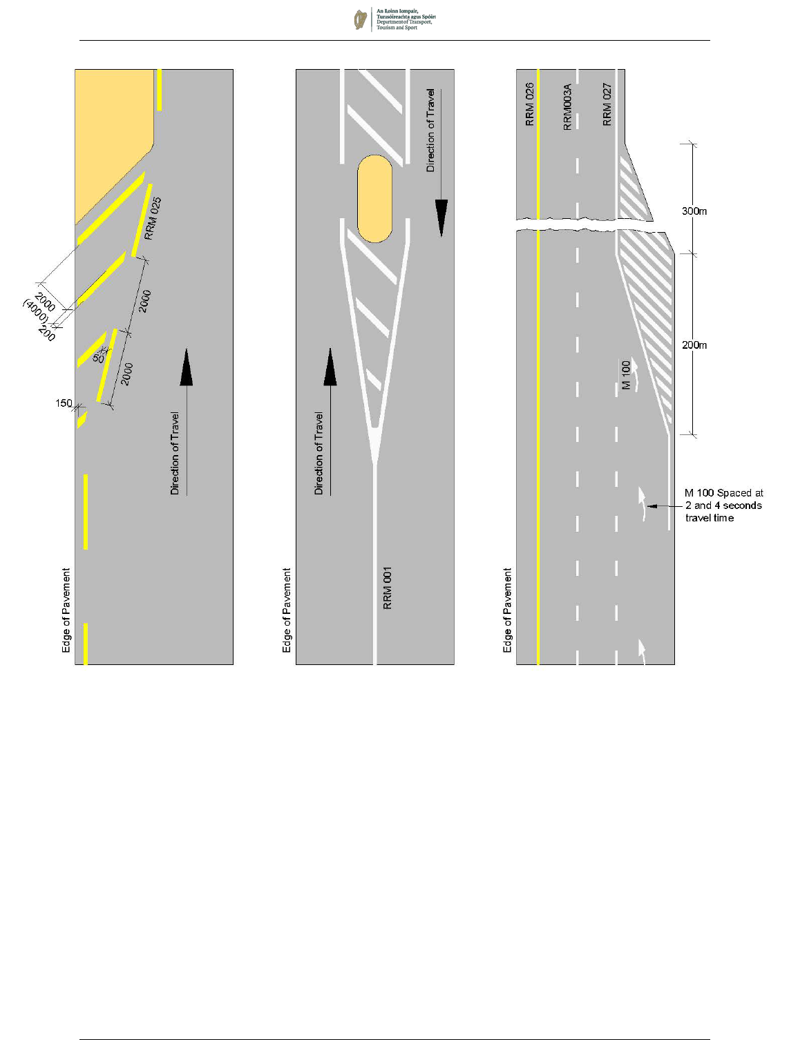
EDGE OF CARRIAGEWAY LINES (RRM 025, RRM 026 & RRM 027)
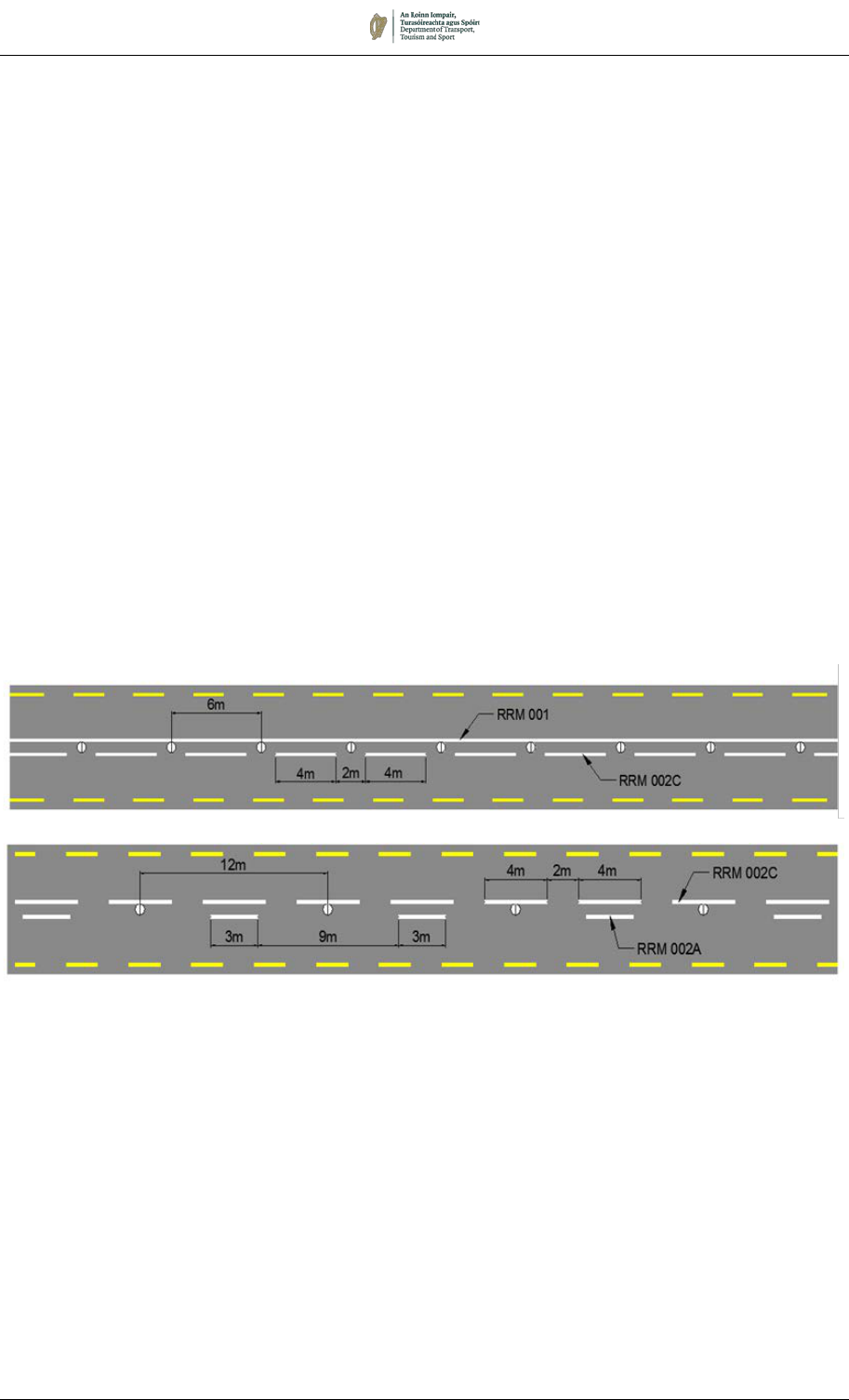
7.3.54 The standard Broken Edge of Carriageway Line consists of a 2m
mark, 2m gap in yellow (RRM 025). A continuous yellow line, RRM
026, is used exclusively on motorways to indicate that trafficking
of the shoulder is not permitted. On the offside edge of motorways
and dual carriageways a continuous white line, RRM 027, shall be
used (See also paragraph 7.3.59). Table 7.4 gives guidance for
the provision of Edge of Carriageway lines.
7.3.55 On rural single carriageway roads, the Broken Edge of
Carriageway Line, RRM 025, is recommended to delineate the
edge of the roadway. It should also be used to delineate the
boundary between the traffic lane and hard shoulder where
provided.
7.3.56 On narrow rural roads where it is not practicable to provide centre
lines (for example, where the carriageway is less than 5.0m in
width) consideration should be given to the laying of Broken Edge
of Carriageway Lines to give drivers a visual indication of the road
alignment. Paragraph 7.3.13 discusses this in greater detail.
7.3.57 The width of the marking depends upon the type of road. In
general, on single carriageway roads, the width of the edge line
should match that of the centre line. The guidance provided in
7.3.13 relating to width of centre line markings, should also be
used for Edge of Carriageway Line width. A 100mm line width is
generally sufficient on narrow roads on which a centre line is not
being provided. On motorways and dual carriageways and
national roads the 150mm width must always be used.
Table 7.4: Provision of Edge of Carriageway Lines
Road Width / Type Rural Urban
< 5.0m Optional No
5.0 – 6.5m Optional Not generally
> 6.5m Recommended Not generally
4-lane Yes
Not generally if kerbed.
Yes otherwise.
Dual carriageway/Motorway Yes Yes
Broken and Continuous
Edge of Carriageway Lines
RRM 025 RRM 026 RRM 027
August 2019 7/29
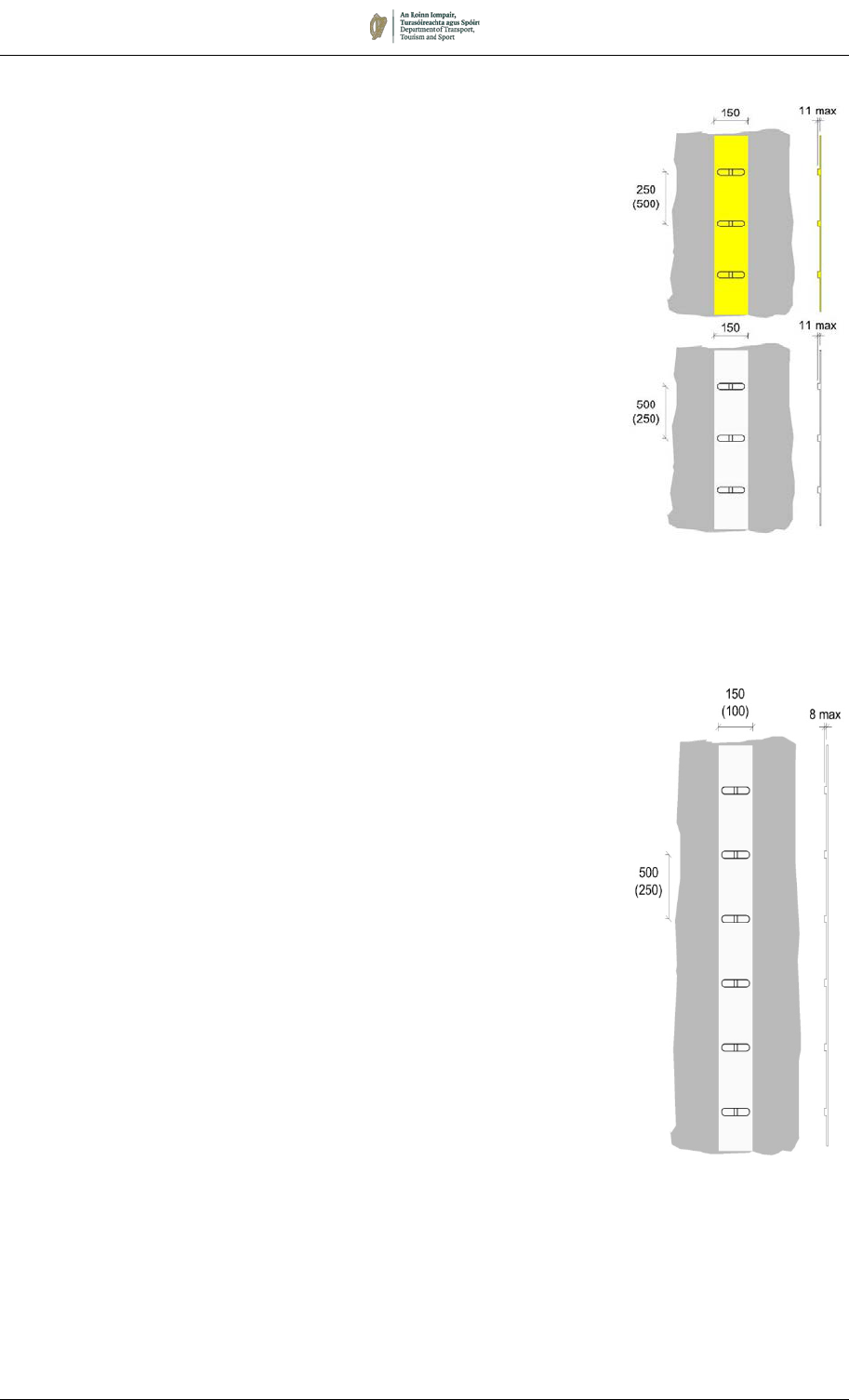
RAISED PROFILE EDGE MARKINGS
7.3.58 Raised profile markings consist of a continuous line marking with
ribs across the line at regular intervals. The vertical edges of the
raised ribs stand clear of the water film in wet conditions, improving
retroreflective performance under headlight illumination. The ribs
also provide an audible vibratory warning to drivers should they
stray from the carriageway and run onto the marking.
7.3.59 Two types of Raised Profile Edge Marking are specified: Type M
for use on motorways and high-quality dual carriageways
(including slip roads) and Type A for use on all other roads, where
the more aggressive rib of the Type M marking would have an
unacceptable effect on cyclists and pedestrians.
Motorways and High-Quality Dual Carriageways
7.3.60 On motorways and high-quality dual carriageways, raised profile
markings Type M to the dimensions shown in Figure 7.8 shall be
used to form the continuous edge of carriageway markings (RRM
026 and RRM 027) including hatch boundary lines (RRM 021).
7.3.61 The base marking shall be no more than 6mm high. The up-stand
of the ribs above the base marking must not exceed 11mm. The
500mm spacing is suitable for most edge lines laid on the main
carriageway, and for continuous boundary lines to hatched areas
(RRM 021). The 250mm spacing is recommended for use on slip
roads, where the closer spacing helps to maintain the rumble
effect, offsetting the likely lower speed. The colour of the markings
shall be either white or yellow as appropriate.
Other Roads
7.3.62 On roads other than motorways and high-quality dual
carriageways, raised profile lines Type A to the dimensions shown
in Figure 7.8 may be used in the following circumstances:
a) Continuous lines indicating the offside edge of carriageway
on a dual carriageway (RRM 027);
b) Continuous bounding line of a diagonal hatched area (RRM
021); and
c) Continuous bounding lines of a chevron hatched area (RRM
021), when used between main carriageway and slip road,
or between bifurcating or converging carriageways (but not
at a roundabout).
7.3.63 The base marking shall be no more than 6mm high. The upstand
of the ribs above the base marking must not exceed 8mm.
7.3.64 Where reflecting road studs are provided as part of a raised profile
marking, the studs may be offset on the trafficked side of the
marking as described in Section 7.10 to provide additional audible
warning to drivers, to facilitate easier maintenance and renewal of
the markings, and to ensure self-cleaning of the studs from over-
running. However, before this arrangement is applied, regard
should be had to the minimum clear lane width as detailed in the
TII design standards.
Figure 7.8:
Raised Profile
Edge Markings
Motorways – Type M
Other Roads – Type
A
August 2019 7/30
7.3.65 Raised profile markings should not be laid where the noise
produced by over-running vehicles is likely to cause annoyance to
residents. Nor should they be used where pedestrians and cyclists
cross the road (e.g. at refuges) or at other places where cyclists
are likely to cross them. In such cases, a plain edge line should be
used instead.
7.3.66 When raised profile markings are renewed, care must be taken to
ensure that the rib height is not increased above the maximum
recommended height.
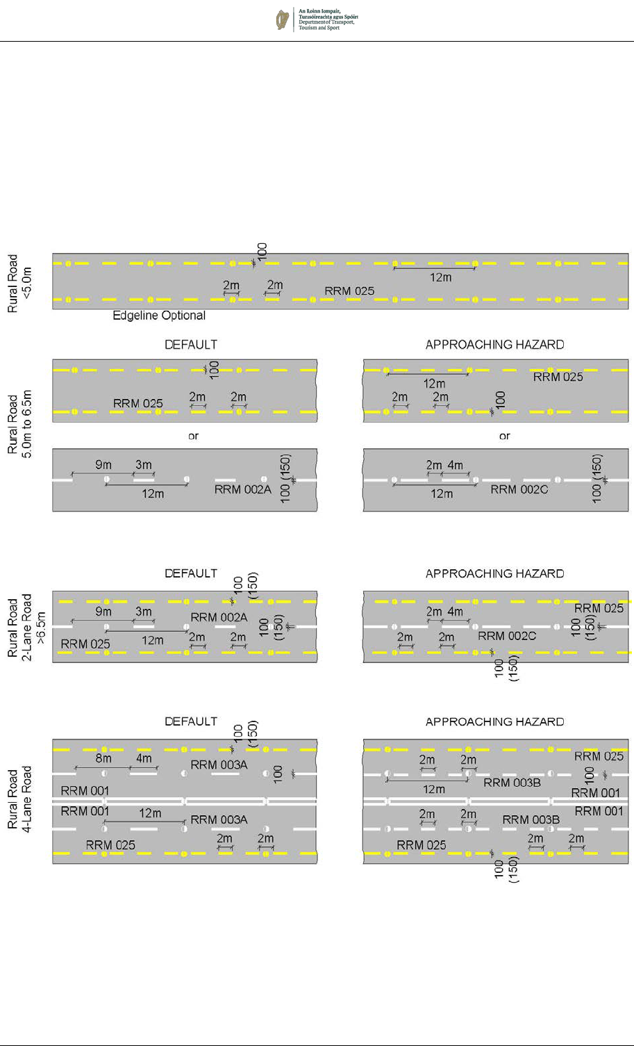
Figure 7.9:
Centre, Lane and Edge Markings for Rural Roads (>60km/h)
August 2019 7/31
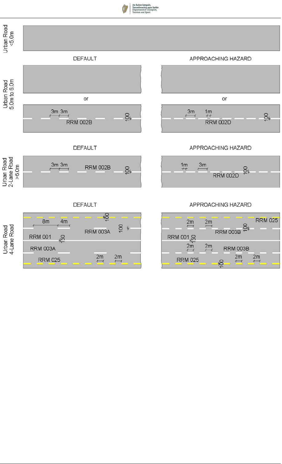
Figure 7.10:
Centre, Lane and Edge Markings for Urban Roads (≤60km/h)
NOTE: Studs are not normally provided when street lighting is present
August 2019 7/32
Figure 7.11:
Centre, Lane and Edge Markings for Dual Carriageways and Motorways (> 60km/h)

August 2019 7/33
7.4 Hatched Markings
7.4.1 Hatched markings (RRM 021) consist of two elements – the
bounding line or lines, which may be Continuous or broken, and
the hatching itself. Hatched markings may be bounded by a
Continuous Line (RRM 001) where entry to the hatched area is
prohibited or by a Warning Line (RRM 002C or D) where entry is
not prohibited. Applications include:
a) the immediate approaches to channelising and central
reserve islands;
b) indication of a reduction in road width ahead;
c) at locations where the road geometry may preclude the
construction of physical islands due to likely over-running by
certain vehicle classes; and
d) other areas which drivers should not enter unless it is safe
to do so.
7.4.2 Boundary line widths and the width and spacing of the hatch lines
are dependent upon the type of road and the speed of traffic.
Specific types of marking exist for motorways and high-speed dual
carriageways, and for other roads. Table 7.5 summarises the
alternative dimensions to be used for given speeds and road types.
However, if this results in a mixture of sizes along a discrete route,
engineering judgement should be exercised to determine the
predominant size to be adopted for the route.
Table 7.5 Dimensions of Hatched Markings
Road / Layout Speed
(km/h)
Boundary
Line
Width
(mm)
Diagonal
Line Width
α
(mm)
Chevron
Line Width
(mm)
Spacing of
Hatch Lines
(mm)
Single or Dual
Carriageway
≤ 60
100 150 200
3000
(6000) †
See Figures
7.16 & 7.17
61 – 100 150 200 500
2000
(4000) †
See Figure
7.18
High Quality Dual
Carriageway or
Motorway
100 – 120 150 500 1000
2000
(4000) *
See Figures
7.13 & 7.14
Widened Central
Reserve
All 150 200 - 4000
See Figure
7.12
Climbing Lanes and
Right-Turn Lanes (See
Section 7.3)
All 150 200 -
2000
(4000) †
See Figures
7.4 & 7.15
† The larger dimensions for hatch spacing may be used when bounded by Warning Lines.
* The larger spacing is for use at central reserve widening.
7.4.3 Where hatched markings are used to separate traffic travelling in
opposite directions, or to deflect traffic from a stationary feature,
diagonal hatch lines shall be used. Where the marking is used to
separate streams of traffic travelling in the same direction chevron
hatch lines are used. With both diagonal and chevron hatched
markings, care must be taken to ensure that the direction of the
hatch relative to the direction of travel of adjacent vehicles is such
as to present a series of transverse lines to vehicles straying into
the hatched area.
August 2019 7/34
MOTORWAYS AND HIGH-QUALITY DUAL CARRIAGEWAYS
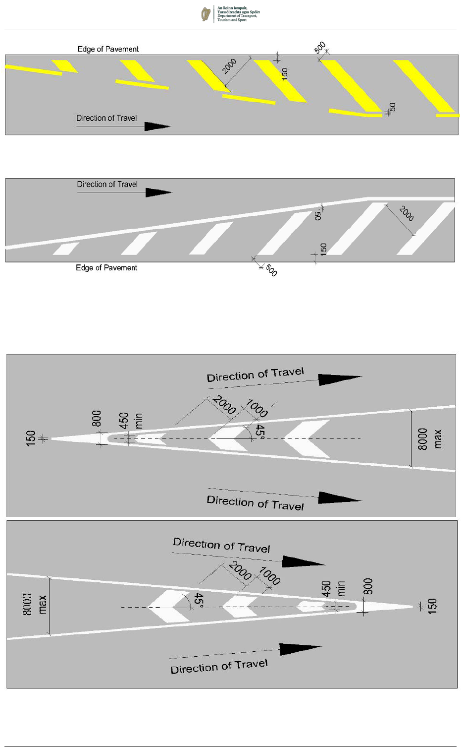
7.4.4 White chevron markings (RRM 021) are the most common hatch
marking on motorways and high-quality dual carriageways, and
are used to divide traffic travelling in the same direction: for
example, at the nosings of merge and diverge lanes. The chevron
hatch line shall have a width of 1000mm at 2m spacing and shall
be bounded by continuous white lines 150mm wide (see Figure
7.14).
7.4.5 Diagonal hatch markings (RRM 021) on motorways and high-
quality dual carriageways will only be appropriate adjacent to the
central reserve in the case of a lane drop, or exceptionally on the
hard shoulder, and shall consist of 500mm wide markings at 2m
spacing (see Figure 7.13).
7.4.6 The boundaries of such diagonal hatched areas shall be
consistent with the prescribed edge markings for the type of road,
as described in Section 7.3. Where hatching is required on the
offside of a motorway or high-quality dual carriageway (for
example at a lane drop – see Figures 7.13 and 7.21), a 150mm
continuous white marking (RRM 027) shall be used to bound the
hatching, and the bounding line and hatching shall be white.
Raised rib markings should be used (on the bounding line only) in
such circumstances.
7.4.7 On high speed dual carriageways, the boundary for diagonal
hatching on the nearside of the carriageway shall be delineated by
a 150mm wide broken yellow marking consisting of a 2m segment
and 2m gap (RRM 025), and the hatching shall be yellow (Figure
7.13). If in exceptional circumstances hatching is required on the
nearside of a motorway, yellow hatching and continuous boundary
lines (RRM 026) shall be used.
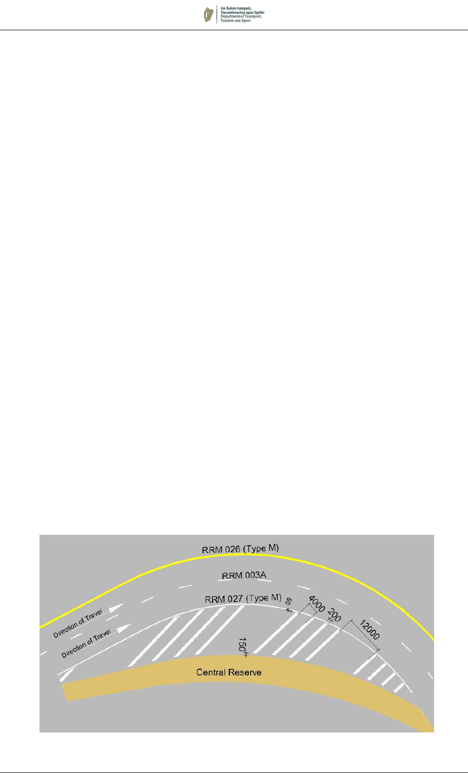
7.4.8 Where a paved central reserve is widened in order to provide the
required stopping sight distance, diagonal hatching should be
provided on the widened reserve. In this location the bounding line
shall be a Continuous White Edge Line (RRM 027) and the
hatching shall be white lines at 4000mm spacing. After each group
of four hatch lines, a gap of 12m may be provided before the next
hatching (see Figure 7.12).
Figure 7.12:
Diagonal Hatched Marking for Use on Widened Central Reserves
August 2019 7/35
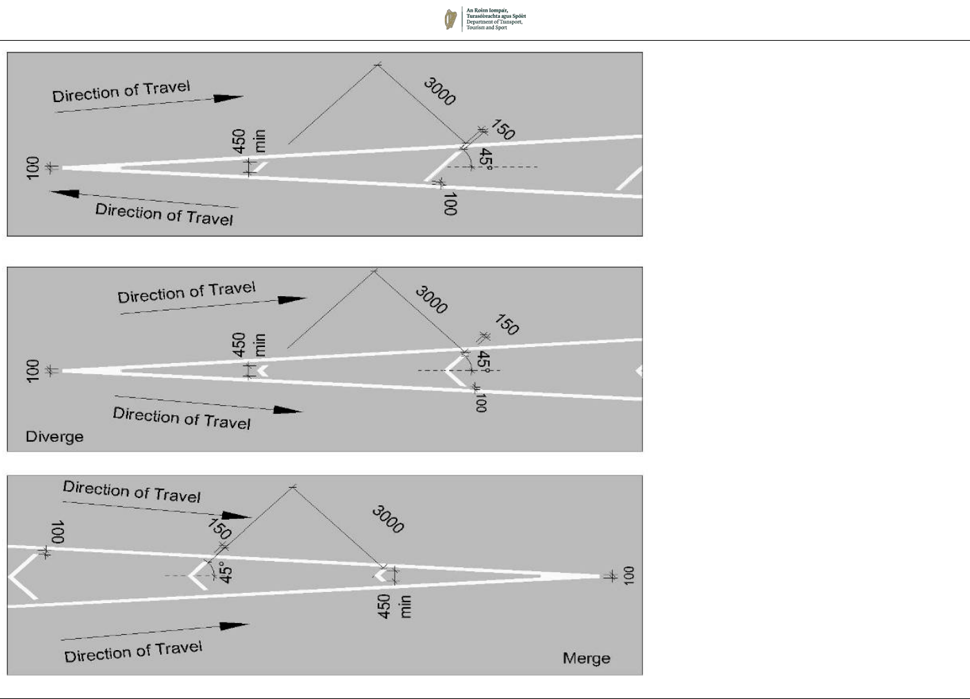
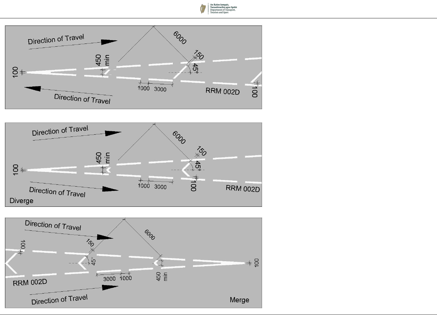
Chevron Markings for Diverging and Merging Traffic on Motorways and High-Quality Dual
Carriageways
Figure 7.14: (RRM 021)
Diagonal Hatched Marking for Use on Offside of Motorways and High-Quality Dual
Carriageways
Figure 7.13: (RRM 021)
Diagonal Hatched Marking for Use on Nearside of High-Quality Dual Carriageways
August 2019 7/36
OTHER ROADS
7.4.9 On single carriageway roads the diagonal hatch is most common;
it is used to separate streams of traffic travelling in opposite
directions. Chevron hatching is used to segregate traffic travelling
in the same direction (for example at splitter islands on one-way
streets). Dimensions of hatched markings are given in Table 7.5.
7.4.10 Hatch lines shall be the same colour as the boundary lines; in most
cases, therefore, hatching will be white. In circumstances where
hatching is bounded by yellow edge lines (such as localised
narrowing on the left side of the carriageway) the hatching shall be
yellow (see Figure 7.19).
7.4.11 It is permitted to use different boundary line types on either side of
a hatched area where appropriate. Figure 7.15 gives an example
of how this could be applied in the vicinity of a short length right
turn lane, where queuing right turning vehicles could impede
straight ahead traffic. It would be acceptable for right turning traffic
to enter the hatched area if the right turn pocket is full, but it would
not be permitted for oncoming traffic to cross into the hatching.
7.4.12 Where there is a large area of hatching bounded by a Warning
Line, the spacing between hatch marks may be increased to the
bracketed dimension shown in Table 7.5.
7.4.13 Figures 7.16 to 7.18 provide a visual guide of which hatching
should be used by road type, and Figures 7.19 and 7.20 illustrate
the application of hatching in various scenarios.
Figure 7.15:
Use of Different
Boundary Lines at a
Limited-length Right
Turn Pocket
August 2019 7/37
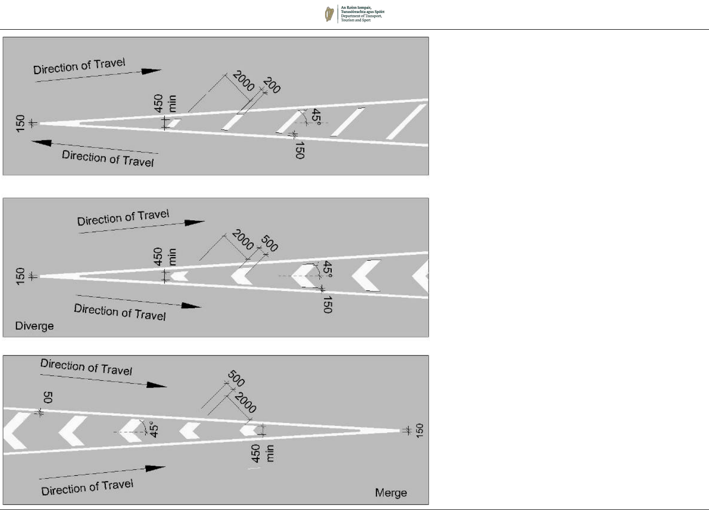
Figure 7.16: (RRM 021)
Hatched and Chevron Markings for Roads
≤ 60km/h
(Continuous Boundary Lines)
August 2019 7/38
Figure 7.17:
Hatched and Chevron Markings for Roads
≤ 60km/h
(Warning Lines)
August 2019 7/39
Note: For hatch dimensions see Table 7.5.
Figure 7.18: (RRM 021)
Hatch and Chevron Markings for Roads
other than Motorways and High-Quality Dual
Carriageways (>60 km/h)
August 2019 7/40
Figure 7.21:
Example of
Motorway Lane
Reduction Markings
Note:
For hatch dimensions see Table 7.5.
Figure 7.20:
Hatched Markings
on the Approach to a
Central Island or
Refuge
Figure 7.19:
Hatched Marking on
Nearside of
Carriageway
on Roads other than
Motorways and High-
Quality Duals
August 2019 7/41
M 114:
Worded STOP
Marking
M 115:
Triangular Yield
Marking
7.5 Worded and Diagrammatic Markings
7.5.1 Various worded markings are prescribed. Some augment
kerbside signs, others indicate areas of the carriageway intended
for a particular function (e.g. Loading), for classes of vehicle (e.g.
Bus), or to be kept clear (e.g. School). The markings are generally
white, but certain diagrams are yellow in colour as indicated.
7.5.2 The basic characters for the capitals, numerals and the
apostrophe are from the Transport Medium Alphabet, elongated to
compensate for foreshortening. There are two standard alphabet
sizes, 1600mm and 2800mm (see Appendix 7A). However, some
worded markings such as ‘TAXIS’, ‘SCOIL’, etc. do not require
such compensation, and therefore use the ‘base font’ of the
Transport Medium Alphabet, scaled to give the overall height
indicated in the various figures.
STOP (M 114)
7.5.3 The worded STOP marking (M 114) may only be used to
supplement the transverse Stop Line (RRM 017) or No Entry Line
(RRM 019) when used at a road junction in conjunction with the
Stop Sign (RUS 027). It must not be used in any other
circumstances, such as at signal-controlled stop lines. The
wording shall be formed from the letters detailed in Appendix 7A;
the height may be 1600mm or 2800mm; the larger size is
recommended for use on high-speed approaches.
TRIANGULAR YIELD MARKING (M 115)
7.5.4 The hollow triangular YIELD marking (M 115) may only be used at
junctions when a transverse Yield Line (RRM 018) or No Entry Line
(RRM 019) is provided and may be accompanied by a Yield Sign
(RUS 026) or Mini-Roundabout Sign (RUS 049). It must not be
used elsewhere.
7.5.5 Where triangular markings are used they should be positioned
approximately in the centre of the traffic lane. Where the approach
to the junction is divided into two or more lanes, a triangular
marking should be provided in each lane.
7.5.6 At the end of a one-way street, triangular YIELD markings should
be laid in each lane to give visual emphasis to drivers of the one-
way operation. This is shown in Figure 7.37 (see Section 7.11).
Worded NO ENTRY markings should not be used.
7.5.7 The Stop and Yield markings should normally be located 2.1m to
2.75m from the associated transverse marking, but exceptionally
this distance may be increased to a maximum of 15m depending
on the visibility at the junction, its layout, and the speed of traffic
on the minor road.

August 2019 7/42
M 106:
SLOW marking
SLOW (M 106)
7.5.8 The worded SLOW marking (M 106) may be used to supplement
a warning sign on the approach to a hazard or road junction. The
marking may be composed of either the 1600mm or 2800mm
lettering: the larger size is recommended for use on high-speed
approaches.
7.5.9 Discretion should be exercised in the use of this marking, to ensure
that its impact is not reduced by proliferation. At particularly
hazardous situations, for example on the approach to a bend at
the end of a long straight section of high-speed road, the marking
may be repeated, with its location related to travel time in a similar
method to that described for deflection arrows in Paragraph
7.5.23.
7.5.10 The location of the marking will depend on the nature of the
hazard. In general, it should be located sufficiently far back to
enable a driver travelling at the normal speed of the road to reduce
speed in time to negotiate the hazard in safety. In some instances,
it may be possible to make use of a change in vertical grade to
position the marking for increased conspicuity.
LOOK LEFT/RIGHT (M 107L/R)
7.5.11 The worded LOOK LEFT and LOOK RIGHT markings (M 107L and
M 107R) are generally intended to warn pedestrians of
approaching vehicular traffic at locations where traffic may be
approaching from an unexpected direction, such as on a one-way
street or between channelising islands. The marking consists of
the words LOOK LEFT or LOOK RIGHT (FÉACH AR CHLÉ or
FÉACH AR DHEIS respectively may be used as an alternative)
painted on the carriageway in 300mm white letters, accompanied
by a white arrow pointing in the relevant direction. It is usually
provided at sites where pedestrians are encouraged to cross.
M 107: LOOK LEFT/RIGHT Marking
Permitted
Variants:
1. The wording shall be LOOK
LEFT, LOOK RIGHT, or
FÉACH AR CHLÉ, FÉACH
AR DHEIS.

August 2019 7/43
ARROWS
Lane Indication Arrows (RRM 004 to RRM 006, M 124 to M 126)
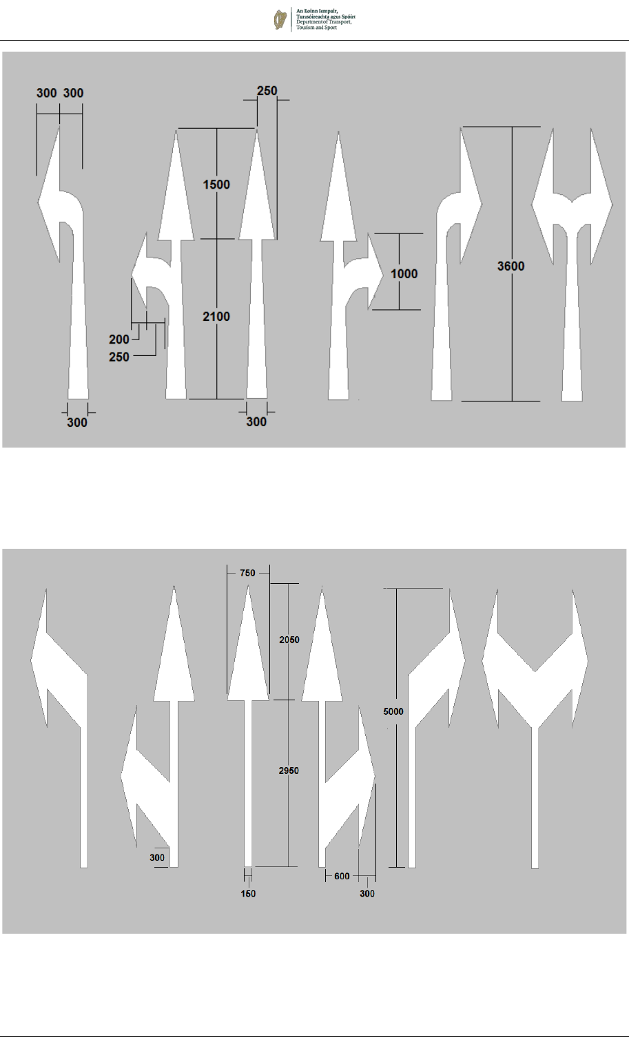
7.5.12 Figures 7.24 and 7.25 illustrate the two-Lane Indication Arrow
types prescribed for use. Generally, with speeds of 60km/h or
less, the arrow types shown in Figure 7.24 should be used. On
faster roads the 5m arrows shown in Figure 7.25 are more
appropriate.
7.5.13 On the approaches to junctions, Lane Indication Arrows may be
used to give drivers advance indication of the correct lane to take.
This is particularly important on the approaches to busy multi-lane
junctions. Traffic must proceed in the direction of the arrow
provided. However, careful judgement is needed to ensure that
such markings are not used inappropriately, as this can reduce the
flexibility of lane usage.
7.5.14 Normally two-Lane Indication Arrows should be used in sequence
in each lane, occasionally three. The one nearest the junction
should be between 15m and 25m from the Stop Line or entrance
to the junction. For speeds of up to 60km/h the second arrow
should be 30m to 50m further back from the first and a third arrow,
if used, should be 30m to 50m back from the second. At speeds
greater than 60km/h, these distances may be increased to the
equivalent of 3 seconds travel time. The direction of each arrow
head may be varied to suit the circumstances, but no more than
two directions may be shown on any one arrow stalk.
7.5.15 On two lane approaches to a junction the arrangement of arrows
indicating the lanes for straight ahead, left-turn and right-turn will
depend on the relative traffic volumes making the movements and
on the site conditions. Where, for instance, there is a very heavy
right turn movement, the straight ahead and left-turn arrows should
be combined in the nearside lane. Similarly, where there is a left
filter arrow in a traffic signal installation, the filter lane should be
marked by the left arrow marking alone in order to exclude non-
filtering traffic.
7.5.16 Lane Indication Arrows may also be used to clarify the direction of
traffic, for example at junctions with dual carriageways and one-
way streets, as described in Section 7.2. However, care should
be taken to avoid imposing conflicting requirements on the driver
by the provision of inconsistent lane indication arrows and, in
particular, side-by-side ahead and right-turn arrows should not be
provided in the same lane on the approach to a junction
August 2019 7/44
Figure 7.24:
Lane Indication Arrows (≤ 60km/h)
Bifurcation Arrows (M 102)
RRM 005 M 124 RRM 004 M 125 RRM 006 M 126
Figure 7.25:
Lane Indication Arrows (> 60km/h)
RRM 005 M 124 RRM 004 M 125 RRM 006 M 126
August 2019 7/45
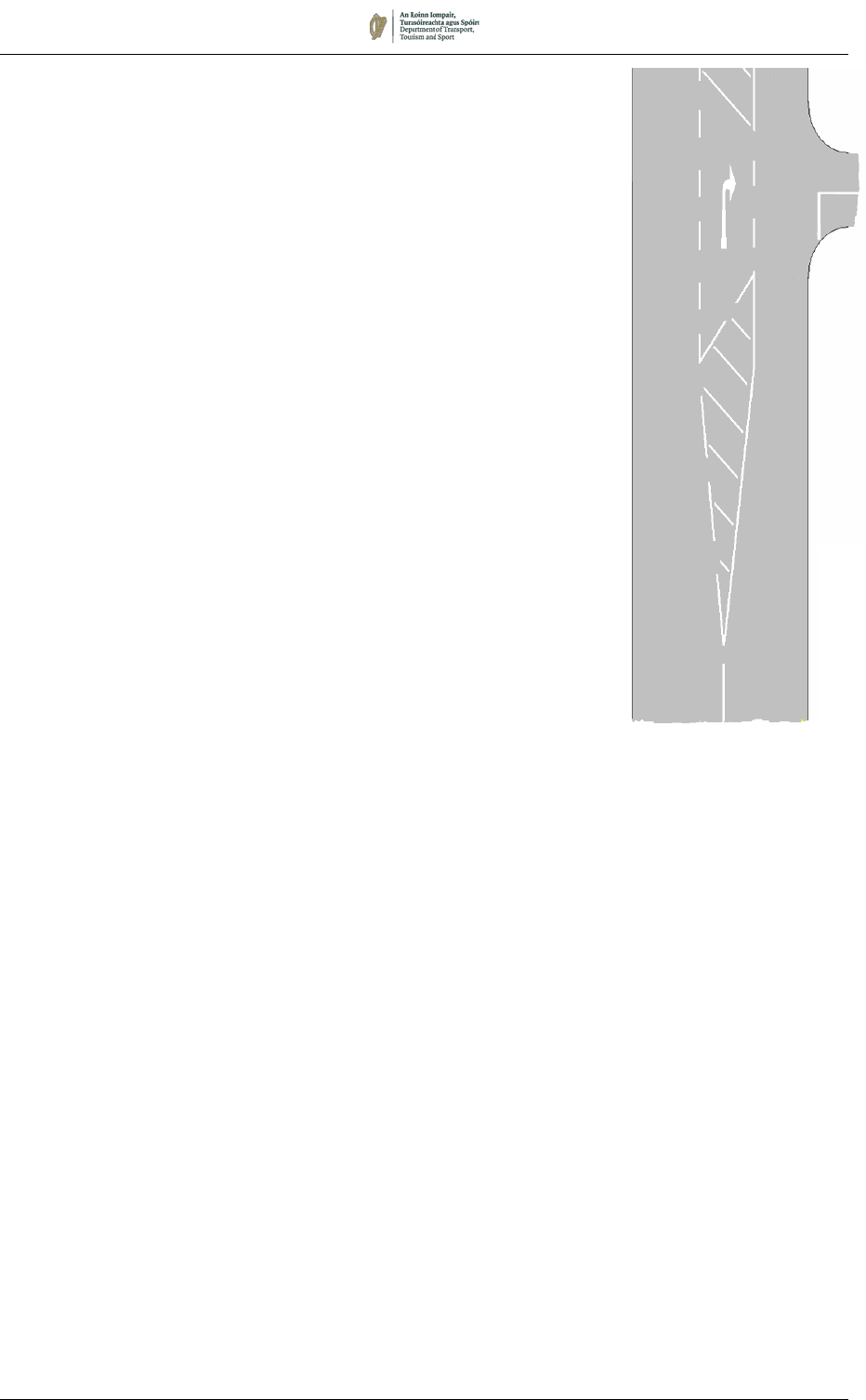
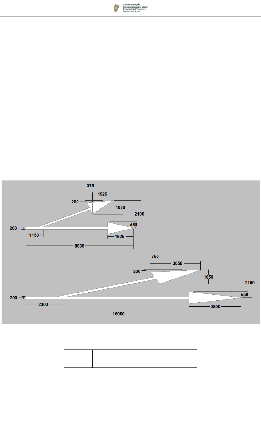
7.5.17 Bifurcation Arrows (M 102) should be provided at the
commencement of deceleration lanes, and at the commencement
of flares leading to dedicated turning lanes on the approaches to
junctions.
7.5.18 Bifurcation Arrows serve to guide vehicles into the deceleration
lane near its commencement ensuring that the full length of the
lane is used to slow down for the junction without impeding through
vehicles on the main carriageway.
7.5.19 The marking may be transposed to suit right turn movements into
deceleration lanes in the central reserve of dual carriageways and
dedicated right turn lanes on other roads.
7.5.20 Three sizes of Bifurcation Arrow are prescribed. The 16m arrow
is generally used on motorways and high-speed dual carriageway
roads, while the 8m arrow is for use on lesser roads. A 32m long
bifurcation arrow (derived by doubling the longitudinal dimensions
only of the 16m arrow) may be used in exceptional circumstances.
M 102: Bifurcation Arrows
Permitted
Variants:
1. The layout may be reversed to show
diverge to the right.
2. The larger arrow may be 32m long.
August 2019 7/46
M 100 & M 101:
Deflection Arrows
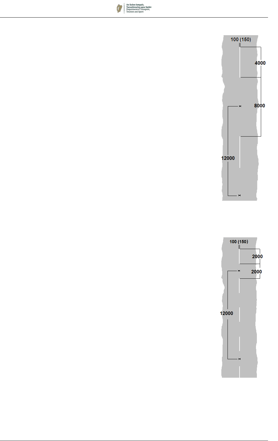
Deflection Arrows (M 100 and M 101)
7.5.21 Deflection arrows (M 100 and M 101) may only be used:
i. Where there is a lane loss, e.g. end of a climbing lane or
start of a bus lane.
ii. In advance of a central hatched area, e.g. start of a climbing
lane or a right turn lane.
7.5.22 The size of the Deflection Arrow is determined by the speed of the
road. The 6m long marking is generally used for speeds of 60km/h
or less and the 9m marking is used on higher speed roads,
although it can also be used where greater emphasis is required.
7.5.23 The Deflection Arrow is positioned at 1 sec (28m @100km/h) in
advance of the end of the lane or Continuous line, a second arrow
is positioned at 2 sec (56m @ 100km/h) travel time in advance of
the first arrow and a third arrow, if required, is positioned a further
2 sec travel time in advance of the second arrow.
7.5.24 The use of the Deflection Arrows is described in Sections 7.3 and
7.7. Although these are non-regulatory markings, it must be
stressed that they should not be used in circumstances other than
those described in the relevant sections. In particular, they should
not be used for the purposes of providing advance warning of a
bend
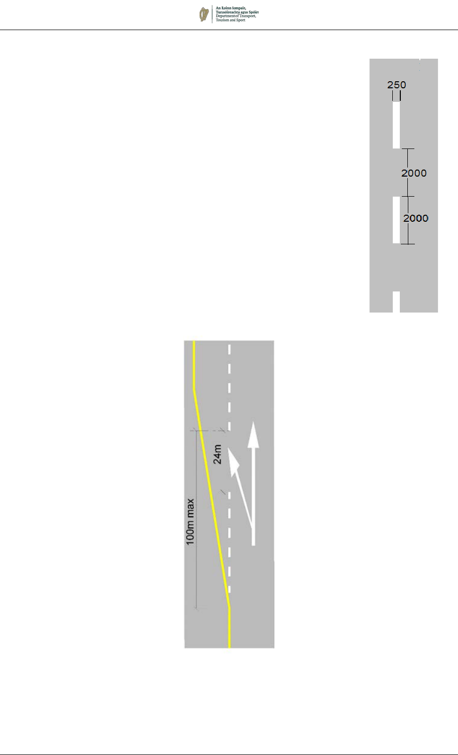
Two-Lane Arrows (M 103)
7.5.25 At the start of either a passing lane section on a Type 3 Dual
Carriageway road or a climbing lane on a single carriageway road,
a Two-Lane Arrow, M103, may be provided to indicate that
vehicles may now overtake
M 103 Two-Lane Arrow

August 2019 7/47
LANE DESTINATION MARKINGS (M 105)
7.5.26 Worded Lane Destination Markings (M 105), repeating the route
information shown on Advance Direction Signs, may, with
advantage, be marked on the carriageway on the approaches to
heavily trafficked junctions. The 1600mm elongated font shown in
Appendix 7A should be used. Lane Destination Markings will
normally be used in conjunction with the 3.6m Lane Indication
Arrows, as at speeds greater than 60km/h the legends would not
be readable. Besides indicating the correct lane to take, the
markings also provide drivers with a useful supplementary
indication to the Advance Direction Sign in the event of the latter
being obstructed by tall vehicles.
7.5.27 For clarity, and avoidance of large areas of thermoplastic material
on carriageways, it is recommended that only route numbers be
marked in this way. To increase legibility on multi-lane
approaches, the destinations may optionally be staggered.
7.5.28 The provision of Lane Destination Markings should normally
commence as far back from the junction as the longest peak hour
traffic queues, unless intervening junctions would lead to
confusion. They may be repeated at intervals between this point
and the associated Stop or Yield Line, in accordance with
Paragraph 7.5.14, but in locations where heavy congestion is
common the distance between successive markings may be
reduced to less than 15m.
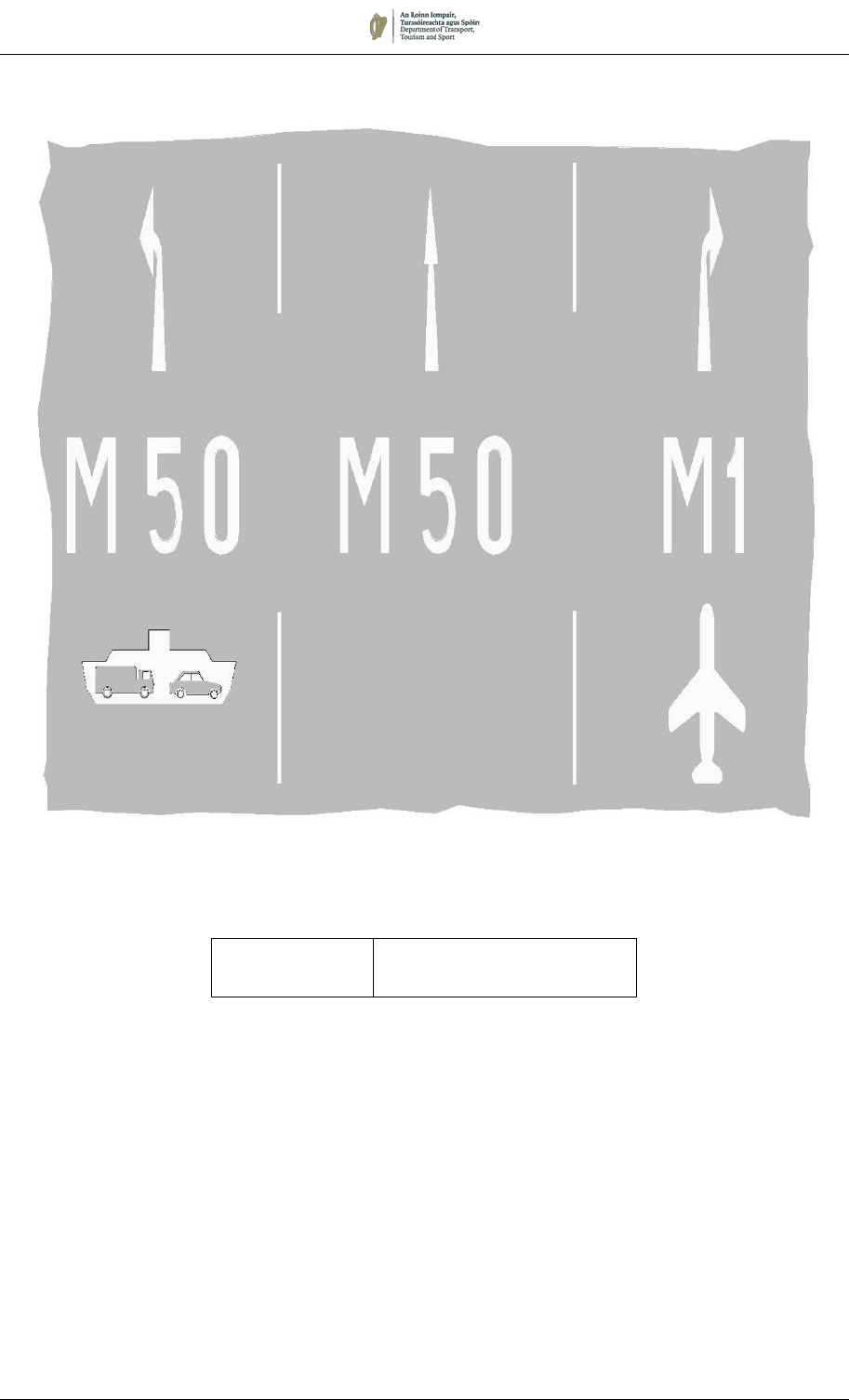
7.5.29 Lane Destination Markings are also available to show Airport (M
127) or Ferry Port (M 128) destinations. The larger size for the
airport symbol is for use on motorways and high-quality dual
carriageways.
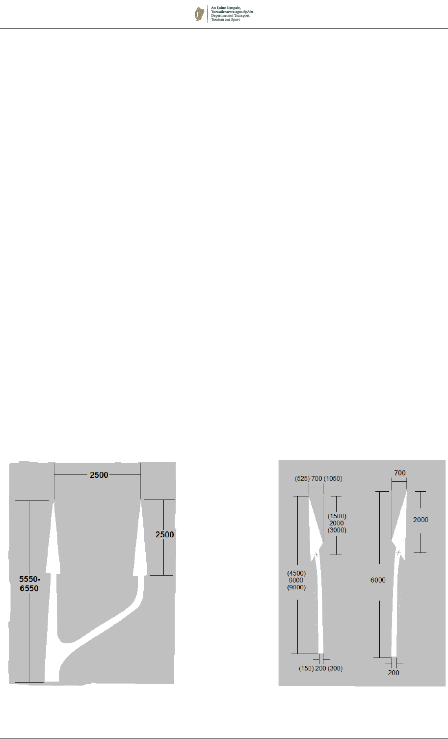
Figure 7.30:
Markings Indicating
the Start of a Bus
Lane
M 127 (4800 x 2400)
Airport Symbol
M 127 (2400x 2400)
Airport Symbol
August 2019 7/48
M 105:
Typical Lane Destination Markings
Permitted Variant:
The road numbers, arrows,
symbols and text may be varied
as required.
Note: Lane Indication Arrows and Ferry and Airport Symbols also shown.
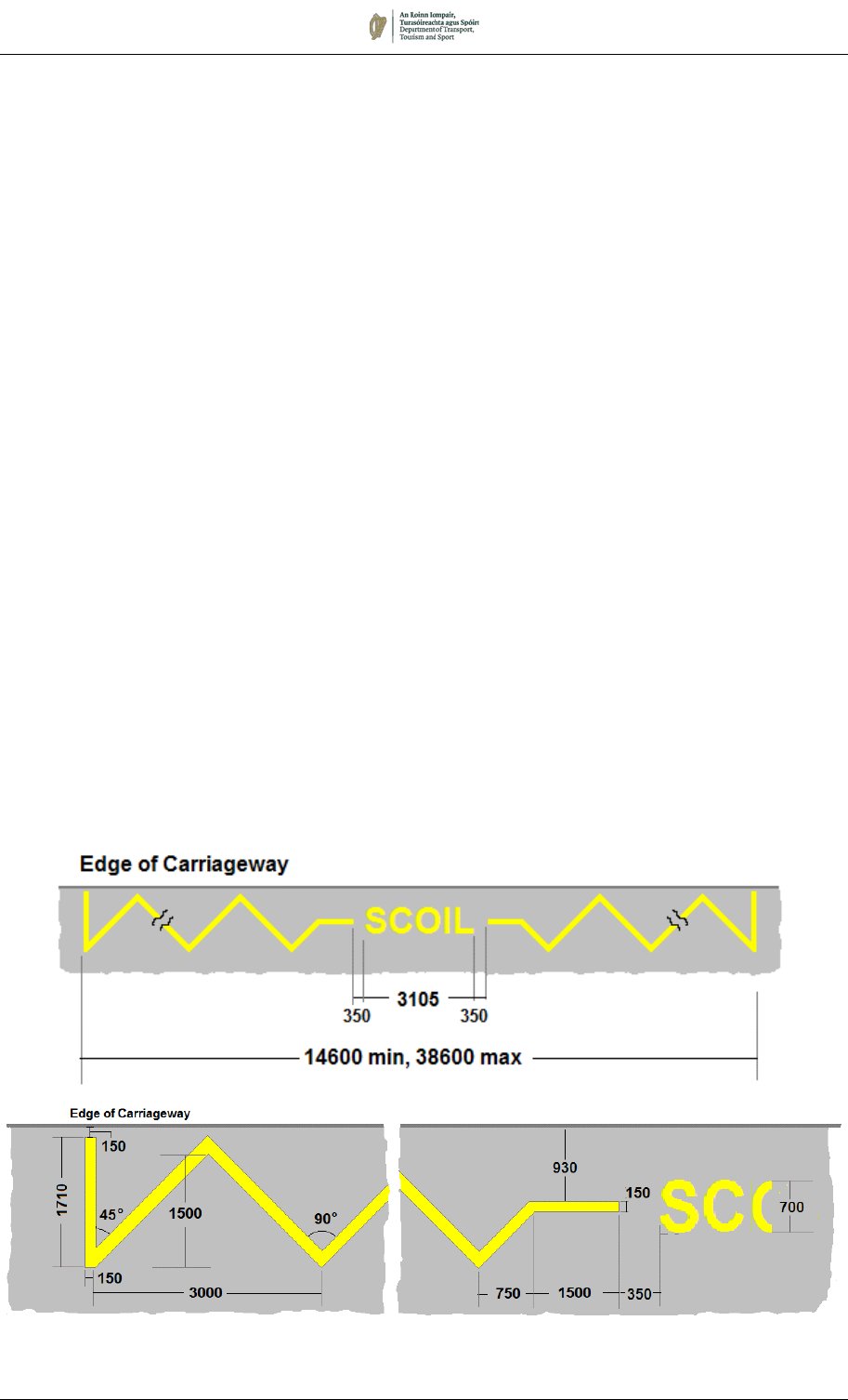
August 2019 7/49
SCHOOL KEEP CLEAR MARKING (RRM 010)
7.5.30 The School Keep Clear Marking (RRM 010) consists of the word
“SCOIL” painted on the carriageway in 700mm yellow letters with
a zigzag pattern of yellow lines, the overall length of which should
not be less than 14.6m (1¼ zigzag markings each side of the
SCOIL wording). The overall length of the marking may be
increased by increments of 6m by the addition of a complete
zigzag pattern on each side of the marking (i.e. overall lengths of
14.6m, 20.6m, 26.6m, 32.6m and 38.6m) up to a maximum length
of 38.6m. A vehicle may not stop or park where this marking is
provided.
7.5.31 The length of the marking needs to be restricted to one which
drivers will respect. Where a Road Authority wishes to lay a
marking with an overall length greater than the maximum 38.6m,
e.g. where the marking is to extend across two entrances which
are wide apart, then two markings of any of the standard lengths
may be joined together, omitting the transverse bars at the join to
form one continuous marking.
7.5.32 Where two separate markings (either single or double as
described above) are required to be laid in close proximity for
school entrances on the same side of a length of road, a clear
space of at least 7m must be left between the markings.
7.5.33 The marking should not normally be placed on both sides of the
road but only the side on which the school entrance is situated.
7.5.34 The markings should not be laid in the controlled areas on the
approaches to pedestrian crossings.
7.5.35 It is not intended that the markings be used outside all schools, but
only where there is a clear need for them because of the hazard
to school children due to parked vehicles.
RRM 010: School Keep Clear Marking
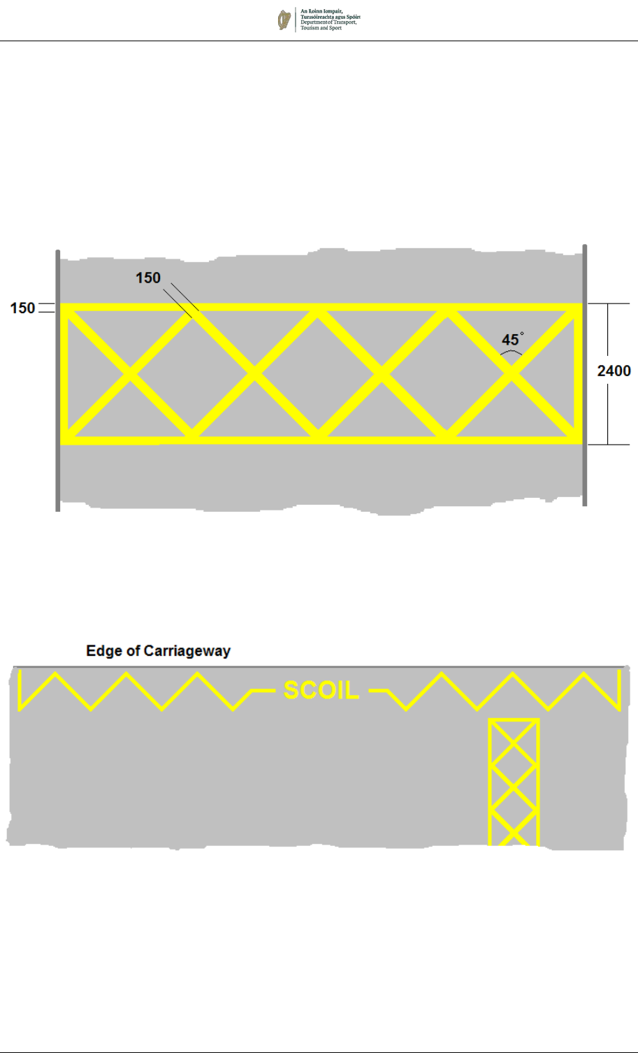
August 2019 7/50
M 121:
School Warden Crossing Patrol Point Marking
Figure 7.26:
Combination of RRM 010 and M 121 Markings
SCHOOL WARDEN CROSSING PATROL POINT (M 121)
7.5.36 Where it is required to indicate the location of a School Warden
Crossing Patrol Point, marking M 121 may be provided.
7.5.37 It is possible that markings M 121 will be used in the vicinity of
RRM 010, School Keep Clear. Figure 7.26 illustrates how the two
markings may be incorporated in such circumstances.
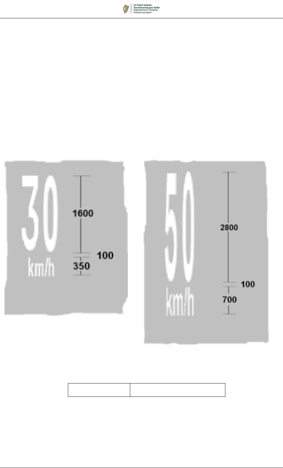
August 2019 7/51
SPEED MARKINGS (M 108)
7.5.38 An indication of the mandatory speed limit may be placed on the
carriageway using the marking M 108. The marking may be varied
to suit the speed limit in force. This marking must not be used to
indicate a cautionary speed.
7.5.39 The marking may be used where a speed limit changes, or in
conjunction with upright repeater signs. It should only be used in
situations where it is necessary to reinforce the upright signing for
reasons of safety, such as the entrance to a village or where an
unexpected reduction in speed limit occurs.
7.5.40 The size of the marking should be appropriate to the approach
speed of traffic, the larger marking being used where approaching
traffic is subject to a speed limit of greater than 50km/h.
M 108:
Speed Markings
Permitted Variant:
Speed may be 30, 50, 60, 80 or
100km/h.

August 2019 7/52
EMERGENCY TELEPHONE AND CHAINAGE MARKINGS (M 120)
7.5.41 On motorways and high-speed dual carriageways, it may be
desirable to provide an indication of the direction to the nearest
emergency telephone. Additionally, chainage markings can aid
the identification of the precise location. This is especially useful
in the event of emergency incidents.
7.5.42 Marking M 120 may be provided on the hard shoulder at intervals
of 100m. The figures indicate the road number, the direction of
travel of that carriageway and the chainage (in the example, the
marking is on Route 4, Northbound carriageway, at chainage
267.5km), and the arrow points in the direction of the nearest
emergency telephone. See Chainage Marker Plates in Chapter 4.
7.5.43 To avoid confusion when providing this information to the
emergency services, it is recommended that the chainage for each
carriageway be measured from the same end of the road
M 120:
Chainage and Emergency Telephone Marking
Permitted Variants:
1. The chainage, direction, and orientation of the arrow may be
varied as required.
2. The telephone symbol and arrow may be omitted on non-
motorway locations or elsewhere where emergency
telephones are not provided.
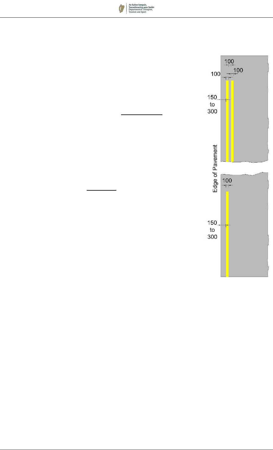
August 2019 7/53
RRM 007
and
RRM 008:
Parking Restriction
Markings
7.6 Parking Restrictions and Parking Bays
PARKING RESTRICTIONS
7.6.1 Yellow lines at the edge of the carriageway are used to define the
extent of parking prohibitions or restrictions. Where appropriate,
the lines must be supplemented by the regulatory signs described
in Chapter 5.
Parking Restrictions – Single Yellow Line (RRM 007)
7.6.2 A continuous Single Yellow Line (RRM 007) indicates that parking
of vehicles is prohibited or restricted at certain times on that side
of the road. The line shall be 100mm wide extending along the
edge of a roadway and situated approximately 150mm to 300mm
from that edge.
7.6.3 The prohibition or restriction, e.g. the times and days, must be
displayed on signs as described in Chapter 5.
Parking Restrictions - Double Yellow Line (RRM 008)
7.6.4 A continuous Double Yellow Line (RRM 008) indicates that parking
of vehicles is prohibited at any time on that side of the road. The
line shall consist of two parallel continuous yellow lines
approximately 100mm apart extending along the edge of a
roadway, each line being approximately 100mm wide and the line
nearest the edge of the roadway being situated approximately
150mm to 300mm from that edge.
7.6.5 There is no requirement to provide upright signs to supplement this
marking. However, it should be noted that if the double yellow line
is laid to reinforce the standard prohibition on stopping within 5m
of a road junction, this may lead to misinterpretation that loading is
generally permitted.
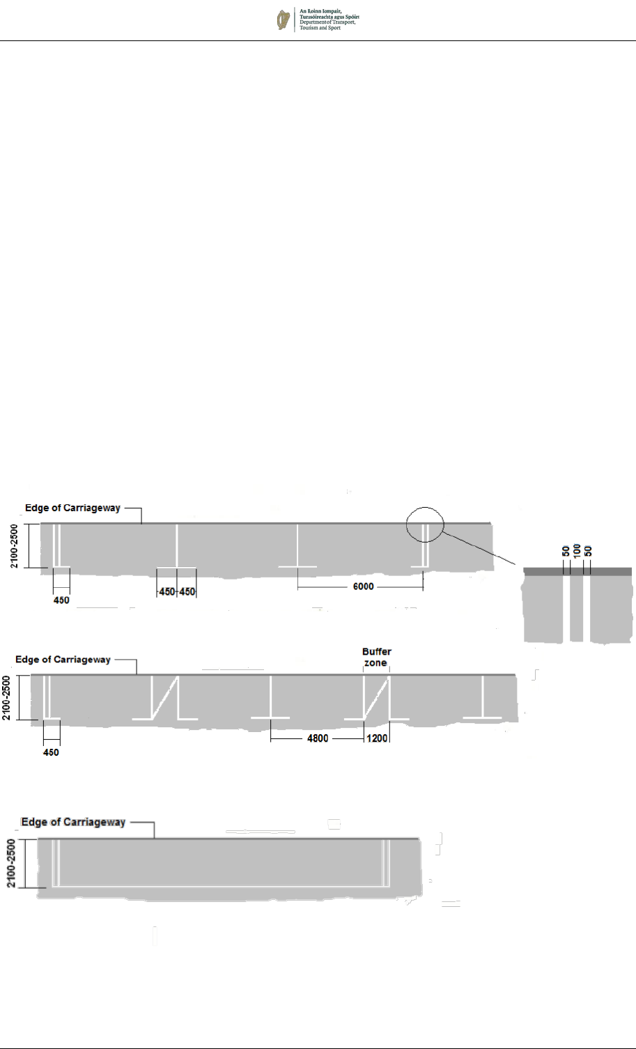
August 2019 7/54
RRM 016:
Parallel Parking Bays: Alternative with No Individual Bays
RRM 011:
Parallel Parking Bays: Individual
RRM 012:
Parallel Parking Bays: Individual with Buffer Zones
PARKING BAYS
7.6.6 Five patterns of parking bay marking are prescribed, three to
indicate the limits for parallel parking, one for perpendicular
parking and one for angled parking bays. All of these markings
may be used outside or inside controlled parking zones. The
markings consist of 50mm wide white lines in all cases.
Parallel Parking (RRM 011, RRM 012 and RRM 016)
7.6.7 Three types of marking are prescribed for parallel parking:
• Individual parking bays, RRM 011;
• Individual parking bays with buffer zones, RRM 012; and
• Continuous parking not marked into individual bays, RRM
016.
7.6.8 In all cases, two continuous terminal markings 100mm apart
indicate the limits of the length of road reserved for vehicle parking.
A single continuous transverse line should be used to mark the
ends of individual parking spaces (RRM 011 and RRM 012).
Where individual bays are not demarcated (RRM 016) a
continuous longitudinal line marks the outer edge of the parking
area. Where appropriate, parking signs (RUS 018 and/or RUS
019) should be mounted at the kerbside to indicate the extents and
periods during which parking is permitted and/or prohibited.
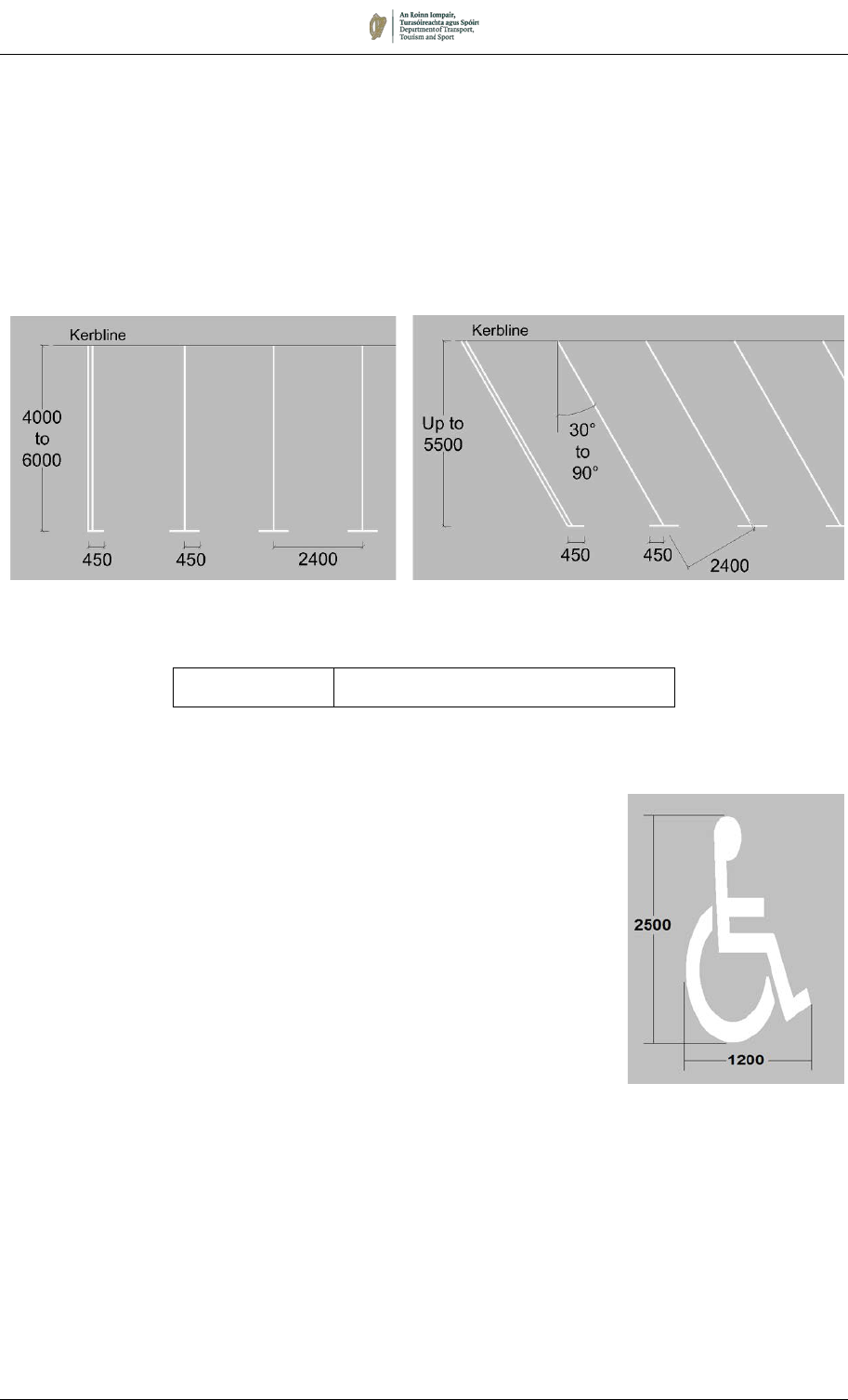
August 2019 7/55
RRM 013:
Perpendicular Parking Bay Markings
RRM 014:
Angled Parking Bay Markings
Perpendicular and Angled Parking (RRM 013 and RRM 014)
7.6.9 The markings for Perpendicular Parking (RRM 013) and Angled
Parking (RRM 014) differ only in the angle of the markings to the
kerb. Individual parking bays are marked, at an angle to the kerb
which may be varied from about 30 to 90 degrees according to the
width of road available. It should be noted that the width of each
bay (2400mm) is non-prescriptive and is given as a preferred bay
width.
Permitted Variant:
The width of parking bays may be varied to
suit specific site conditions.
Disabled Persons’ Parking (RRM 015)
7.6.10 Parallel, angled or perpendicular Disabled Persons’ Parking Bays
may be provided in isolation, or as part of a series of parallel,
angled or perpendicular parking bays. The dimensions of disabled
persons’ bays are shown in Figure 7.27, together with examples
of how the markings may be incorporated with adjacent parking
bays.
7.6.11 Care should be taken to ensure that adequate space is provided
between a disabled persons’ parking bay and adjacent parking
bays to permit a wheelchair to be manoeuvred safely. It is
recommended that buffer zones be provided as shown to permit
easy access. Note that when two or more disabled persons’
parking bays abut, the buffer zone between them can be shared.
7.6.12 Disabled persons’ parking bays shall be indicated by the Disabled
Persons’ Parking Bay Symbol, RRM 015, marked in white and
located on the outer edge of each bay, and may be accompanied
by the upright Disabled Persons’ Parking information sign (F 205
– see Chapter 4). The bays may also have blue surfacing applied
within the limits of the bay, but this should not be extended into the
adjacent carriageway or any buffer zones. The provision of
dropped kerbs should also be considered to enhance accessibility.
RRM 015:
Disabled Persons’
Parking Bay Symbol
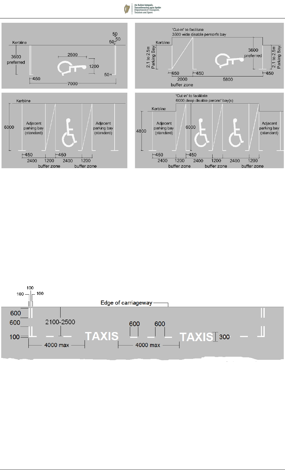
August 2019 7/56
Figure 7.27: Typical Examples of Disabled Persons’ Parking Bays
TAXI STAND (RRM 029)
7.6.13 A Taxi Stand is indicated by the markings to RRM 029 shown
below. The lines forming the taxi stand shall be white and 100mm
wide. The wording ‘TAXIS’ shall appear at least once in each
stand, repeated at intervals of not more than 4m, and shall be
parallel to the kerb and facing towards the centre of the roadway.
The terminal points of the taxi stand shall be indicated by double
broken markings consisting of 600mm lines and 600mm gaps
perpendicular to the kerb.
RRM 029:
Taxi Stand Markings
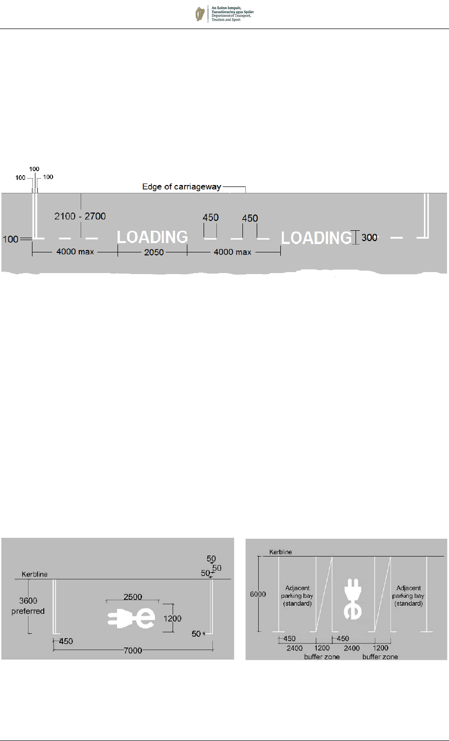
August 2019 7/57
LOADING BAY (RRM 009)
7.6.14 A Loading Bay is indicated by the markings to RRM 009 shown
below. The lines forming the loading bay shall be white and
100mm wide. The wording ‘LOADING’ shall appear at least once
in each loading bay but shall be repeated on bays greater than
10m in length and shall be parallel to the kerb and facing towards
the centre of the roadway. The terminal points of the loading area
shall be indicated by double continuous lines perpendicular to the
kerb.
ELECTRIC VEHICLE RECHARGING BAY (RRM 034)
7.6.15 An Electric Vehicle Recharging Bay is indicated by road marking
RRM 034, marked in white and located on the outer edge of each
bay and should be accompanied by the upright Electric Vehicle
Parking Bay regulatory sign (RUS 020a – see Chapter 5). The
bays may also have green surfacing applied within the limits of the
bay, but this should not be extended into the adjacent carriageway
or any buffer zones.
7.6.16 Parallel, angled or perpendicular Electric Vehicle Recharging Bays
may be provided in isolation, or as part of a series of parallel,
angled or perpendicular parking bays. The dimensions of such
bays are shown in Figure 7.27, together with examples of how the
markings may be incorporated with adjacent parking bays.
RRM 009:
Loading Bay Markings
RRM 034:
Electric Vehicle Recharging Bay Markings
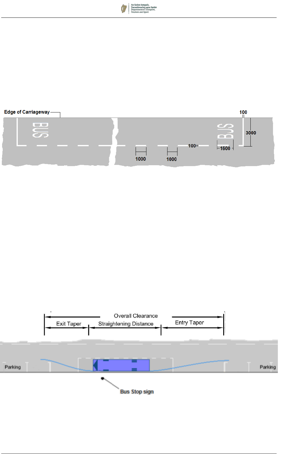
August 2019 7/58
Figure 7.28:
Clearance at Bus Stop Required for Parallel Docking (12m Rigid Bus)
RRM 030:
Bus Stop Markings
7.7 Bus and Tram Markings
BUS STOP (RRM 030)
7.7.1 Bus Stop Markings, RRM 030, shall only be used to indicate the
location of a bus stop, where they supplement a kerbside upright
Bus Stop Sign (RUS 031), or to indicate the location of a bus stand.
They indicate the area within which vehicles other than buses may
not stop or park.
7.7.2 It is important that buses should be able to dock parallel to and
close to the kerb, to assist passengers, particularly those with a
mobility handicap, to board and alight with ease. This can
frequently be made difficult, especially in urban areas, by a variety
of factors, some of which may be overcome by careful design.
7.7.3 The major factor in achieving parallel docking at a bus stop is the
entry and exit distance required. At a typical roadside bus stop, a
conventional 12m European standard bus requires a minimum
overall clearance of 37m of unimpeded access (see Figure 7.28);
an articulated bus needs 49m. Vehicles parked or loading
adjacent to the bus stop can result in buses failing to achieve
parallel docking or having to stop too far from the kerb, requiring
passengers to step into the carriageway to board and alight.
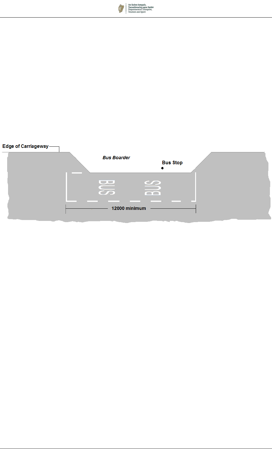
August 2019 7/59
Figure 7.29:
Bus Stop Marking at a Bus Boarder
7.7.4 The extent of the bus bay marking should, therefore, be
determined after careful consideration of the site, including
demands for kerbside parking and loading activities. It is
suggested that the parking and loading restrictions adjacent to bus
stops should be reviewed to ensure that the bus stop is accessible
to buses throughout their operating period.
7.7.5 There are instances where site conditions make a short Bus Stop
Marking acceptable, for example where a bus boarder has been
constructed to minimise the impact of the bus stop on frontage
parking (see Figure 7.29). In these cases, the bus bay marking
should be no shorter than the length of the bus type that uses it
(12m in the case of a standard bus).

August 2019 7/60
Figure 7.30:
Markings Indicating
the Start of a Bus Lane
BUS LANES
7.7.6 Bus lanes may be either ‘with-flow’ or ‘contra-flow’, and the
markings used in each case are described in the following
paragraphs. The associated regulatory signs are shown in
Chapter 5.
7.7.7 The edge(s) of the bus lane that segregate(s) it from lanes of
general traffic shall be marked by a continuous white Bus Lane
Line, part of RRM 024, which shall be 250mm wide.
With-Flow Bus Lanes
7.7.8 A 250mm wide Broken Bus Lane Line, M 129, shall be laid from
the kerb to the start of the full width lane to deflect other traffic from
the bus lane (see Figure 7.30). The taper at which the line is laid
should not normally exceed 1:10, but in exceptional cases may be
reduced to 1:5.
7.7.9 Where general traffic has to be deflected to the right, Right
Deflection Arrows, M 101, shall be provided on the nearside lane
about 15m and 30m in advance of the start of the bus lane.
7.7.10 Where a bus lane commences just beyond a junction, adequate
length should be left for the taper to commence at the junction so
that the inclined line does not extend across the junction mouth.
7.7.11 The legend LÁNA BUS, part of RRM 024, shall be marked on the
carriageway across the lane close to its start and repeated after
each junction. Where junctions are more than 300m apart this
legend should be repeated between junctions at approximately
150m intervals.
7.7.12 Where a side road joins on the nearside of the road, the
Continuous Bus Lane Line, part of RRM 024, should be
discontinued across the junction or, if required, replaced with a
Broken Bus Lane Line, M 129, across the junction.
7.7.13 Beyond each junction carrying emerging traffic, a curved Broken
Bus Lane Line, M 129, should be provided across the bus lane to
continue the line of a normal left-turn out of the side road (see
Figure 7.32).
7.7.14 The Continuous Bus Lane Line should end in advance of any
junction with a major left-turning flow, to allow traffic to position
itself correctly on the carriageway. The continuous line should be
replaced by a Broken Bus Lane Line with a double-headed Bus
Lane Ends Arrow variant, M 130L, placed to inform motorists that
it is permissible to enter the bus lane prior to making the left-turn.
7.7.15 At the end of a bus lane, a double-headed Bus Lane Ends Arrow,
M 130, should be provided to indicate that the nearside lane may
be used by all traffic. In cases where the nearside lane is restricted
to left turning traffic, the left-turn variant M 130L should be used.
If the offside lane becomes a right-turn only lane, the right turn
variant M 130R should be used.
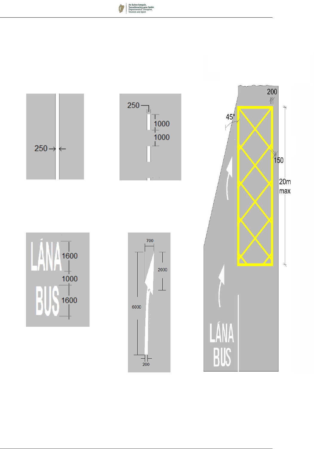
August 2019 7/61
M 101:
Right Deflection Arrow
Part of RRM 024:
Continuous
Bus Lane Line
M 129:
Broken
Bus Lane Line
Part of RRM 024:
Worded LÁNA BUS
Marking
Figure 7.31:
Yellow Box Markings at
the End of a Bus Lane
7.7.16 In cases where obstruction by other traffic makes it difficult for
buses to re-enter the general traffic stream at the end of a bus
lane, Yellow Box Markings (RRM 020) may be provided as shown
in Figure 7.31 (see also Section 7.9).
7.7.17 A composite sketch showing typical treatment for a with-flow bus
lane is shown in Figure 7.32.
20m
max
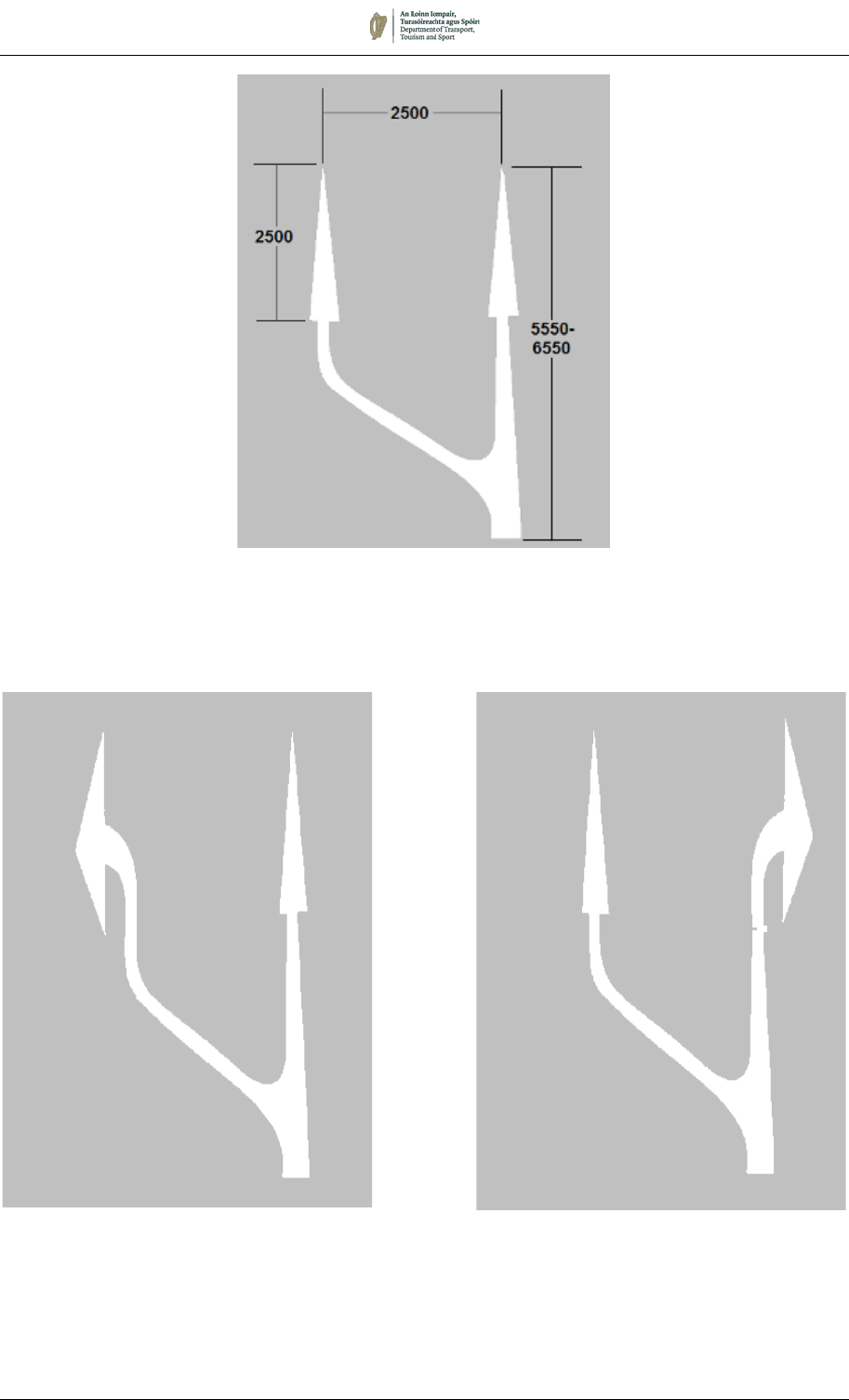
August 2019 7/62
M 130:
Double-headed
Bus Lane Ends Arrow
M 130L M 130R
Left and Right Turn Variants of
Bus Lane Ends Arrow
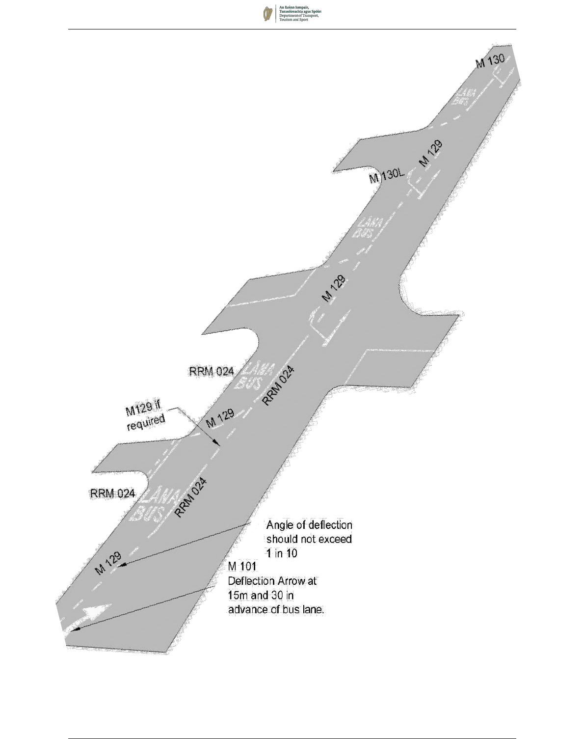
August 2019 7/63
Figure 7.32:
Typical Road Markings for a With-Flow Bus Lane
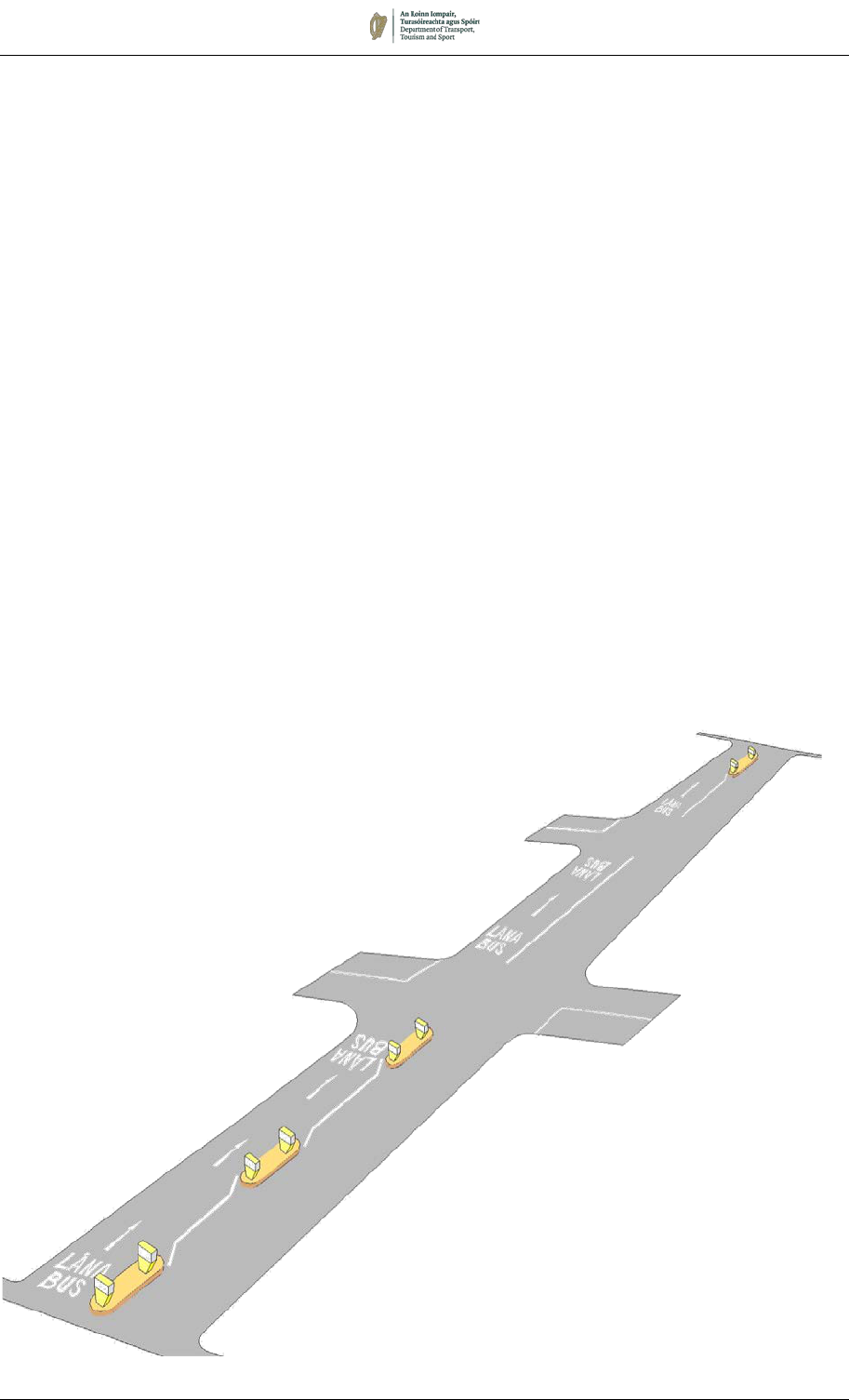
August 2019 7/64
Figure 7.33:
LÁNA BUS Worded Markings
Used in a Contra-flow Bus Lane at a Junction
Contra-flow Bus Lanes
7.7.18 The road markings are as described for with-flow bus lanes, with
a continuous Bus Lane Line, part of RRM 024, separating the bus
lane from other lanes. However, additional ‘LÁNA BUS’ worded
markings, together with Directional Arrows, RRM 004, should be
provided in such locations that they are readable by road users
travelling in the direction of general traffic or joining from side roads
(see Figure 7.33).
7.7.19 Physical separation is advisable between the contra-flow bus lane
and general traffic. This can either be a continuous kerbed Island
or pedestrian refuges at appropriate intervals. While ensuring that
other vehicles do not enter the lane, this may introduce potential
difficulties, such as:
• Causing pavement rutting if the lane is narrow; and
• Creating difficulties for buses having to take avoiding
action in emergency or breakdown.
7.7.20 At the beginning of a contra-flow bus lane, a No Straight
Ahead sign (RUS 011) should be used with Supplementary
Plate P 050, Except Buses (see Chapter 5).
7.7.21 Contra–flow bus lanes should not normally be less than 3.0m wide.
7.7.22 Directional Arrows, RRM 004, or LOOK LEFT/RIGHT Markings, M
107L/R, may be laid at pedestrian crossing points, to warn
pedestrians that traffic may be approaching from both directions.
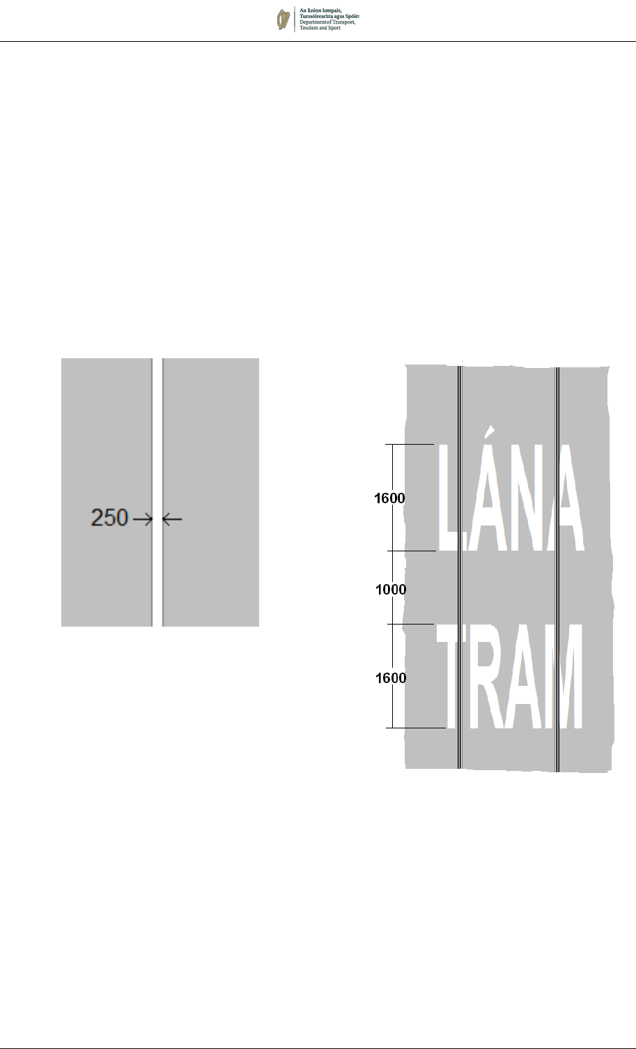
August 2019 7/65
M 109:
LÁNA TRAM Worded Marking
TRAM LANES
7.7.23 Where trams (Light Rapid Transit vehicles) operate on the
carriageway adjacent to lanes trafficked by other vehicles, the
extent of the tram lane shall be indicated by a 250mm wide
continuous white line or lines (RRM 032), except where this
coincides with the centre line of a roadway between the tram way
and an adjacent traffic lane.
7.7.24 To clarify the area of carriageway used by trams, the ‘LÁNA TRAM’
Worded Marking, M 109, should be laid at appropriate locations,
in the same manner as LÁNA BUS Worded Markings.
RRM 032:
Continuous Tram Lane Boundary Line
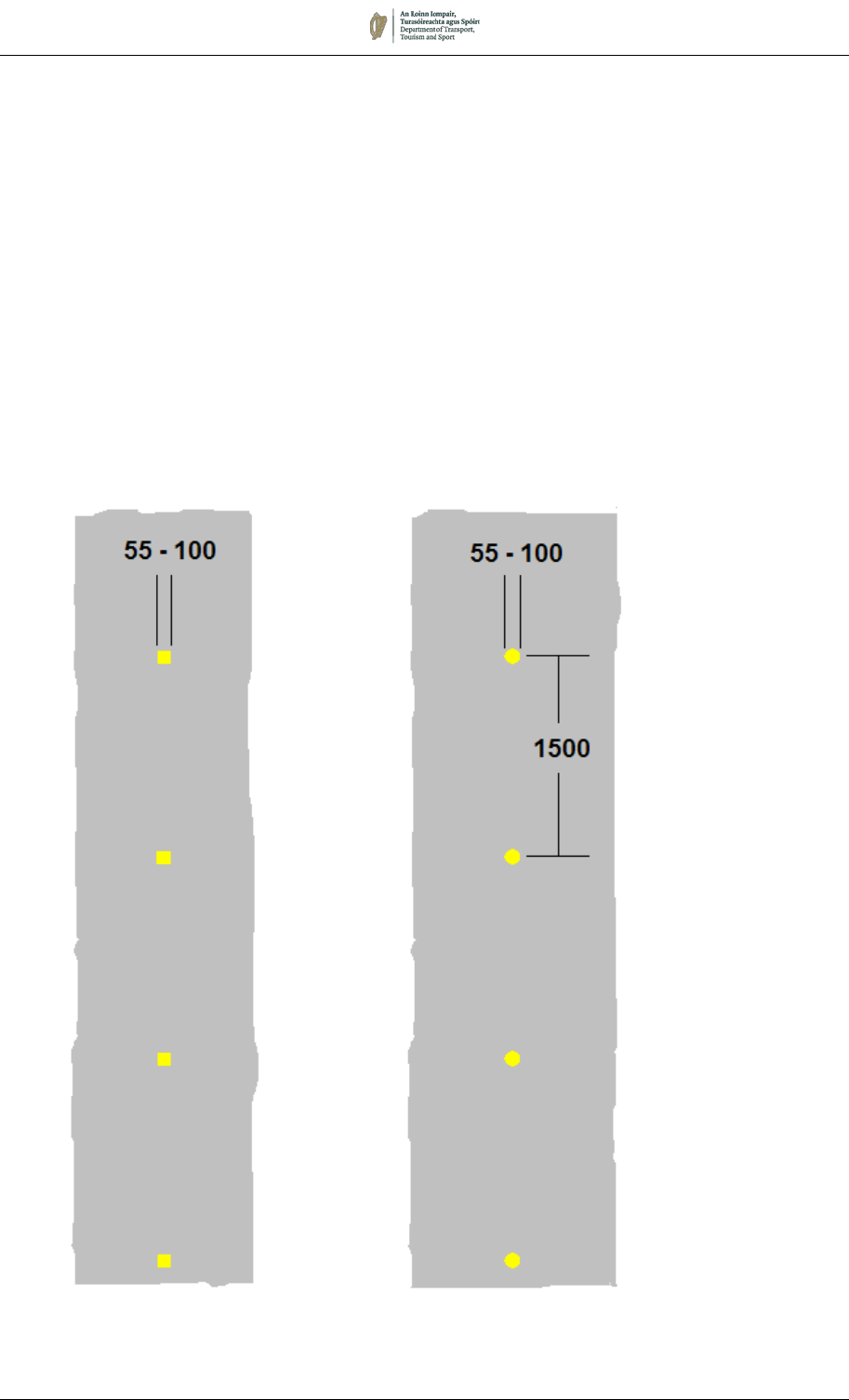
August 2019 7/66
7.7.25 Light Rapid Transit vehicles are normally significantly wider than
the tracks on which they run, and the degree of overhang
increases on curves and with tram motion. It is, therefore,
necessary at some locations to indicate the area of the
carriageway which will be occupied by the tram. This area is
referred to as the ‘swept path’.
7.7.26 The tram driver needs to be able to identify whether the tram’s
swept path is clear of vehicles. In some places, the swept path
can be indicated by the Tram Lane Line, RRM 032, or Yellow Box
Markings, RRM 020. However, these markings could cause
confusion to other drivers at some locations, such as junctions and
sharp curves. The Swept Path Marking, M 110, is available for
use in such circumstances. The marking consists of round or
square yellow marks of between 55mm and 100mm diameter or
width, spaced at 1.5m intervals. The markings need to be
positioned on or just outside the edge of the swept path; close
liaison with the light rail operator will be required to ensure that the
swept path envelope is accurately delineated.
M 110:
Light Rail Swept Path Marking

August 2019 7/67
7.8 Cycle Tracks
7.8.1 The markings prescribed for use in cycle tracks are:
• Cycle Track Edge Line, RRM 022:
• Cycle Track Broken Edge Line, RRM 023:
• Cycle Track Yield Line, RRM 018C;
• Cycle Track Triangular Yield Marking, M 115C
• Cycle Track Direction Arrows, M 117, M 118, M 119;
• Cycle Symbol, M 116; and
• Pedestrian Symbol, M 111.
7.8.2 Cycle track markings may be used in conjunction with other road
markings and should be accompanied by the regulatory signs
specified in Chapter 5.
7.8.3 Cycle track markings are white, and some are smaller versions of
markings used for general traffic. These include 1800mm long
direction arrows (M 117, M 118 and M 119) and reduced-scale
Broken Edge Line (RRM 023) and Yield (RRM 018C and M 115C)
markings. These markings are used when specific cycle facilities
have been provided. See also the Advanced Cycle Stop Line
described in Section 7.2.
WITH-FLOW CYCLE TRACKS
7.8.4 Where a cycle track is marked on the nearside of the carriageway,
the outer edge should be indicated by a continuous white Cycle
Track Edge Line, RRM 022, 100mm wide (150mm on roads with
traffic speeds greater than 60km/h). Other vehicles are prohibited
from crossing the line. If the cycle track is only operative during
certain periods, or where it is necessary for general traffic to cross
the boundary of the cycle track (for example, across a priority
junction or on the approach to an Advanced Cycle Stop Line), a
Cycle Track Broken Edge Line, RRM 023, should be used on
either side.
7.8.5 The Cycle Symbol, M 116, should be marked on the carriageway
across the cycle track at its commencement and repeated after
each junction. The symbol, which is available in two sizes, should
be repeated at intervals and may be supplemented by a Direction
Arrow, M 118. The Cycle Track Broken Edge Line, RRM 023,
consisting of a 100mm (or 150mm) wide broken marking with
750mm lines and 750mm gaps, should be laid from the kerb to the
start of the full width cycle track to deflect other traffic from the
cycle track.
7.8.6 One or two Right Deflection Arrows, M 101, should be provided on
the approach to the start of a cycle track, except in the case of a
short ‘feeder’ lane leading to an Advance Stop Line.
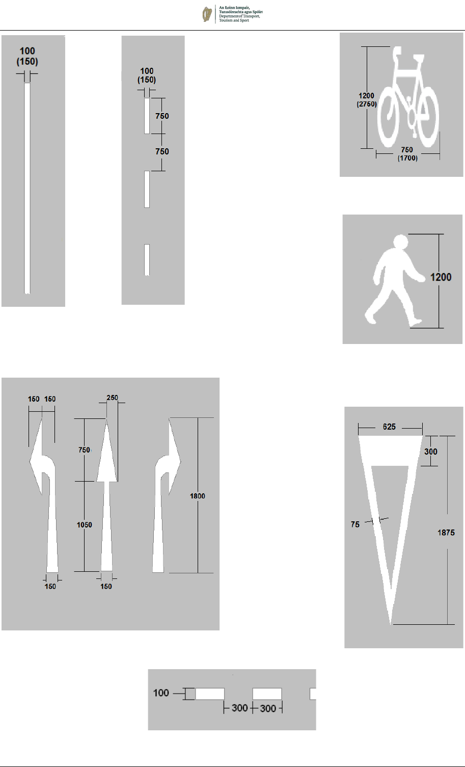
August 2019 7/68
M 116 – Cycle Symbol
RRM 022
Edge Line
RRM 023
Broken Edge
Line
RRM 018C
Cycle Track Yield Line
M115C
Cycle Track Yield
Marking
M 111 – Pedestrian
Symbol
M 117 M 118 M 119
Cycle Track Direction Arrows

August 2019 7/69
7.8.7 Where a cycle track is marked on a rural road with no hard
shoulder and no street lighting, it is recommended that the yellow
bi-directional studs that would normally be located on the edge
marking (RRM 025) should instead be located on the trafficked
side of the cycle track marking (RRM 022), approximately 25mm
to 50mm from the line.
CONTRA-FLOW CYCLE TRACKS
7.8.8 A contra-flow cycle track may be designated on a road which is
one-way to all other traffic. These shall be designed such that
cyclists using the track observe the required rules of the road
(specifically, that they should keep to the left of the carriageway,
whilst oncoming traffic passes to their right).
7.8.9 Generally, there will be physical separation between the cyclists
and oncoming vehicles at the commencement of such a cycle
track, either by refuges, islands or other kerbed features to provide
an entry gate, which may be repeated at intervals. Between such
features, the cycle track shall be segregated from the opposing
traffic lane by a 150mm wide Continuous line RRM 022. In
addition, arrows to M 118 and cycle symbols to M 116 shall be
provided at intervals of not more than 100m, and at any point
where it is necessary to clarify to all road users the direction of the
cycle track.
7.8.10 At junctions, the edge of the cycle track shall be designated by
RRM 023 for that section where general traffic crosses the cycle
track.
7.8.11 Special regulatory signing is required for contra-flow cycle tracks.
This is described in Chapter 5.
7.8.12 Examples of with-flow and contra-flow cycle tracks are shown in
Figure 7.34.
CYCLE TRACKS NOT ON THE CARRIAGEWAY
7.8.13 Where a segregated cycle track is provided on a footway or
footpath, the cycle track may be delineated either by means of a
pair of parallel RRM 022 markings indicating the limits of the cycle
track, or by a single continuous marking RRM 022 indicating the
division of the path into cycle track and footway. The Cycle
Symbol, M 116, should be provided at the commencement of the
cycle track and at intervals along it. The Pedestrian Symbol, M
111, should also be provided on the pedestrian section of the path,
adjacent to the Cycle Symbol.
7.8.14 The use of Cycle Track Direction Arrows (M 117, M 118 and M
119), the Pedestrian Symbol (M 111) and the Cycle Track Yield
Line and Triangle (RRM 018C and M 115C) are discretionary and
should be used to clarify priorities and directions of flow as
appropriate. Similarly, the Cycle Symbol (M 116) may be used in
addition to the specific applications described in Paragraph 7.8.5
to clarify the operation of shared or segregated cycling facilities.
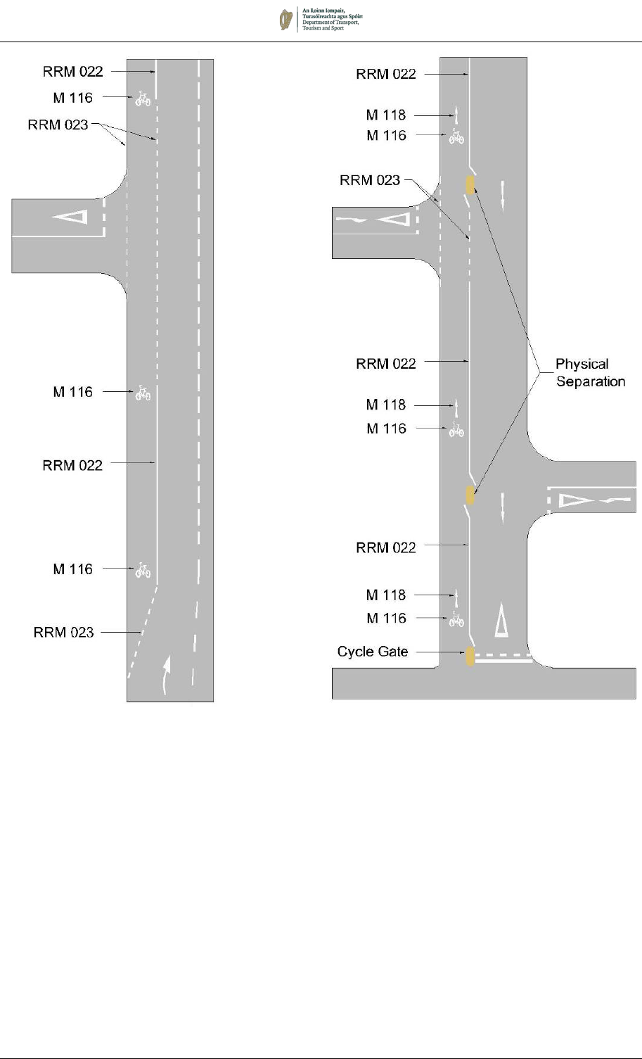
August 2019 7/70
With-flow Cycle Track Contra-Flow Cycle Track
Figure 7.34:
Sample Cycle Track Layouts

August 2019 7/71
7.9 Yellow Box Markings
7.9.1 Yellow Box Markings, RRM 020, are provided to aid traffic flow.
They may be used at road junctions (including roundabouts), at
junctions with tram tracks, at railway level crossings, the exits to
bus lanes, or other locations as deemed appropriate by the road
authority, where blocking back affecting a cross flow is a significant
problem.
7.9.2 The carriageway is marked with yellow lines to form a box
enclosing yellow cross-hatched diagonal lines.
7.9.3 Not all locations are suitable for treatment and it is necessary to
apply certain criteria before deciding whether a particular site
should be marked. The following points would be relevant:
Yellow boxes are expensive to maintain and should be used
only where other solutions will not work.
Linked signals can help to keep a junction clear. In addition, it
is possible to provide detectors at a location after a vehicle
passes through a junction. This can pick up ’tailbacks’ from
the next junction and prompt the traffic signals to change thus
preventing obstruction of the junction by vehicles.
Sometimes a yellow box is not needed at a junction controlled
by signals but is needed at an adjacent junction which does
not have signals and is affected by queues from the signal-
controlled junction.
The carriageway beyond the yellow box should be free from
obstruction (this may require the imposition of parking
restrictions or the relocation of a bus stop).
Where a succession of locations gives rise to blocking a series
of yellow boxes may be considered provided at least 20m
storage can be maintained between successive boxes.
There should preferably not be a high proportion of right
turning vehicles.
7.9.4 The use of half boxes (in which only half the area of the junction is
marked) is appropriate at “T” junctions and other locations where
traffic only blocks back from one direction only.
Layout
7.9.5 The boundaries of a yellow box marking are formed by 200mm
wide continuous yellow lines. Two diagonal lines join opposite
corners, or projected corners, of the box, and lines are then drawn
parallel to each diagonal to form cross-hatched marking in yellow.
The diagonal lines are 150mm wide and spaced 2000mm apart
where the shortest boundary line of the box is 9000mm or less,
and 2500mm apart where the shortest boundary line of the box is
greater than 9000mm. Box junctions should usually have four
straight sides transverse to the traffic flow on the approaches,
although up to 10% of the length of any side may be cut away as
shown in the diagram to accommodate corner kerbs. The overall
shape of the marking and the number of cross hatching lines will
vary to accord with the circumstances at the site.
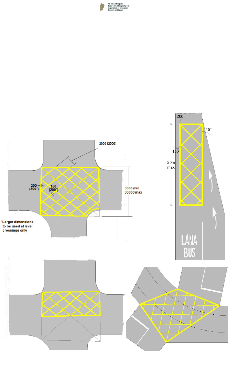
August 2019 7/72
Special Cases
7.9.6 When used at a railway level crossing, the boundary markings
shall be 300mm wide, and the diagonal markings 200mm wide.
Section 7.15 provides further details.
7.9.7 Where a Light Rapid Transit (LRT) line enters a road used by
general traffic, it may be advantageous to install a yellow box to
maintain free access for the LRT vehicles. In such cases, the
boundary lines of the box may follow the swept path envelope of
the LRT vehicle.
7.9.8 Where there is an identified issue of general traffic blocking the
exit from a bus lane, a yellow box may be laid to provide a facility
for buses to enter the general traffic stream (see also Figure 7.31).
In this circumstance, the diagonal lines shall form an angle of 45º
with the direction of travel.
RRM 020:
Yellow Box Markings

August 2019 7/73
7.10 Reflecting Road Studs
7.10.1 Road studs shall comply with EN Standards and should be of a
type approved for use by Transport Infrastructure Ireland for
national roads, or the Department of Transport for other roads.
7.10.2 In urban speed limit zones, where street lighting is provided, studs
will not generally be necessary. However, in the case of higher
speed urban and rural roads and rural national roads, lit and unlit,
all centre lines, lane lines, edge of carriageway lines and hatching
should have reflecting road studs on the mainline and on all
associated road links such as slips, interchange links and loops.
7.10.3 The standard spacing of studs for various line types are given in
Table 7.6. The following paragraphs provide greater detail on the
types of stud for specific applications and note where special
spacing would be appropriate.
Table 7.6: Road Stud Spacings
Marking Reference
Stud
Colour
Uni/Bi-
directional
Stud
Spacing (m)
Notes
Centre
Line
Continuous
RRM 001
White
Bi
6
See 7.10.4 for
Double Line Systems
See 7.10.7
Broken
RRM 002A
RRM 002B
12
Warning
RRM 002C
RRM 002D
12/6
Lane
Line
RRM 003A White
Uni
12
RRM 003B
White /
Green
12/8
See 7.10.6 for stud
colour and spacing
RRM 028
Green
8
Edge
Line
RRM 025
Yellow Bi / Uni
12
Bi-directional on
single carriageway;
uni on dual and
ramp.
Green /
Yellow
Bi
Single carriageway
junction approach;
See 7.10.9.
Green Uni
Dual carriageway
and ramp junction
approach;
See 7.10.9.
RRM 026
RRM 027
Yellow Uni
Hatched
Markings
RRM 021
White or
Yellow
Uni 12/8/6
See 7.10.11 and
7.10.12

August 2019 7/74
7.10.4 Double Line System. For the standard double line markings,
white reflecting bi-directional studs should be laid centrally
between the lines. If a Double Line System contains a Continuous
Line, the stud spacing should be 6m; it should otherwise be 12m.
Where lines are splayed to enclose a hatched area between them,
the studs should be located in both of the lines, should be uni-
directional, and should be spaced as appropriate to the more
restrictive boundary line type.
7.10.5 Broken Centre Line (RRM 002A and B). White reflecting bi-
directional road studs should be placed centrally within line gaps
at 12m spacing.
7.10.6 Lane Lines (RRM 003A and B). Where lane lines are indicated
white uni-directional studs should be placed centrally within line
gaps at 12m spacings. Where right turn pockets and left turn
deceleration lanes are indicated, green uni-directional studs
should be placed centrally within gaps at 8m spacings (on the left-
hand side only in the case of a right-turn lane).
7.10.7 Warning Lines (RRM 002C and D). White reflecting bi-directional
studs should be placed centrally within line gaps at 12m centres.
However, where Warning Line is used in lieu of extensive sections
of Continuous Line on lower quality rural roads, as described in
7.3.24, studs may be at 6m centres.
7.10.8 Merge/Diverge Lane Lines (RRM 028). Where Merge/Diverge
Lane Lines indicate the division between the nearside lane of a
high-quality dual carriageway or motorway and a merging or
diverging lane, green unidirectional studs should be placed
centrally within line gaps at 8m spacing.
7.10.9 Edge of Carriageway (RRM 025, RRM 026 & RRM 027). Where
studs are provided at the nearside edge of carriageway in
combination with a Broken Edge of Carriageway Line, RRM 025,
they should be yellow, bi-directional (except on dual carriageways,
where uni-directional should be used) and placed centrally within
line gaps at 12m centres.
13 green studs should be provided at 12m centres on RRM025
Edge Lines in advance of junctions (bi-directional green/yellow on
single carriageways; uni-directional green on dual), but not when
they are otherwise provided on adjacent lane lines. In the case of
single carriageways, they should be provided on both approaches
to the junction arm on the side on which the junction is located.
See Figures 7.38 to 7.40. The Continuous Edge of Carriageway
Line, RRM 026 and RRM 027, should have uni-directional yellow
studs at 12m centres.
7.10.10 The studs may be offset from the continuous edge lines RRM 026
and RRM 027 by 25mm on the trafficked side of the marking. This
is especially appropriate when raised profile markings are used,
as the studs provide additional audible warning to drivers of the
edge of carriageway. Offsetting the studs also facilitates easier
maintenance of the road markings, and the increased level of over-
running by traffic contributes to self-cleaning of the lenses.
However, before this arrangement is applied, regard should be
had to the minimum clear lane width as detailed in the TII design
standards.

August 2019 7/75
7.10.11 Hatched markings. Stud provision is determined by the type and
colour of the bounding lines, and the location of the lines.
Continuous boundary markings should be provided with reflecting
uni-directional studs at 6m spacing. On Warning boundary lines,
the spacing should be 12m. If greater conspicuity is required 8m
or 6m spacing may be used for urban and rural roads respectively.
7.10.12 On Motorways and high-quality dual carriageways, yellow uni-
directional studs should be provided at 6m centres on the
boundary to chevron-hatched areas.
Hazard Markers
7.10.13 Where the provision of road studs at the edge of carriageway is
impracticable (for example, on narrow rural roads with thin
pavement), Hazard Markers (W 180) may be provided instead.
These are reflectors mounted on short posts in the verge and are
described in Chapter 6.
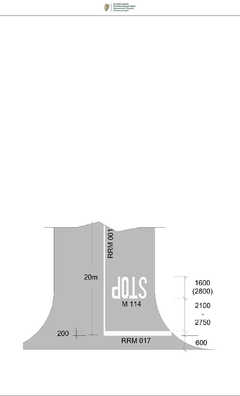
August 2019 7/76
Figure 7.35: Example of Priority-Controlled Stop Junction
Note: See Paragraph 7.11.2
7.11 Priority Junctions
7.11.1 Road markings at priority junctions consist of transverse markings
indicating the requirement to stop or yield, together with
associated centre lines and other markings to guide and inform
drivers of the junction layout. In the case of a one-way street, the
No Entry Marking, RRM 019, shall be used.
7.11.2 The edge of the transverse line nearest to the major road should
not be closer than 600mm to the line of the back of the paved area
of the major road. On two-way roads, the Stop or Yield Line, RRM
017 or RRM 018, must be accompanied by a central Single
Continuous Line, RRM 001, normally extending longitudinally back
from the junction for a minimum distance of 20m from the
transverse line, but this may be reduced to 8m as site conditions
require. However, on roads less than 5.3m wide this distance may
be reduced to 2m (see Section 7.2).
7.11.3 Additional markings may be provided on the minor road to
supplement the transverse markings as appropriate. These
include the worded STOP Marking, M 114, and the triangular Yield
Marking, M 115.
7.11.4 On the major road, Warning Lines, RRM 002C or D, may be used
in place of the standard Broken Centre Line, RRM 002A or B, to
emphasise the junction to drivers on the major road.
7.11.5 Figures 7.35 to 7.37 illustrate the layout of some simple junctions.
Figures 7.38 and 7.39 show typical edge line treatments at
junctions where the main road has a hard shoulder.
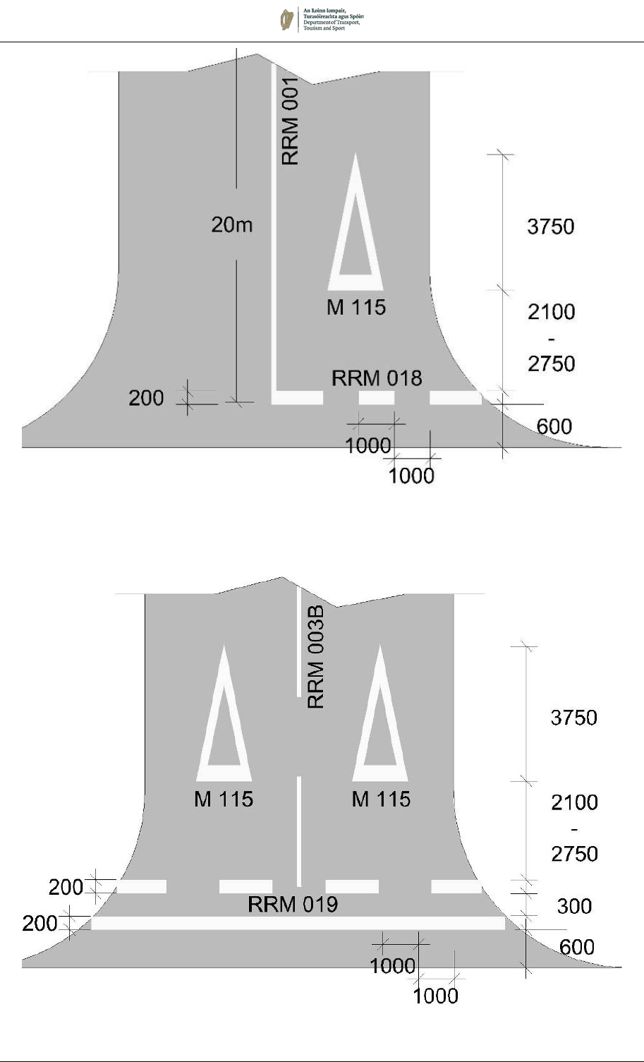
August 2019 7/77
Figure 7.37: Example of Markings at Mouth of One-way Street
Note: See Paragraph 7.11.2
Figure 7.36: Example of Priority-Controlled Yield Junction
Note: See Paragraph 7.11.2
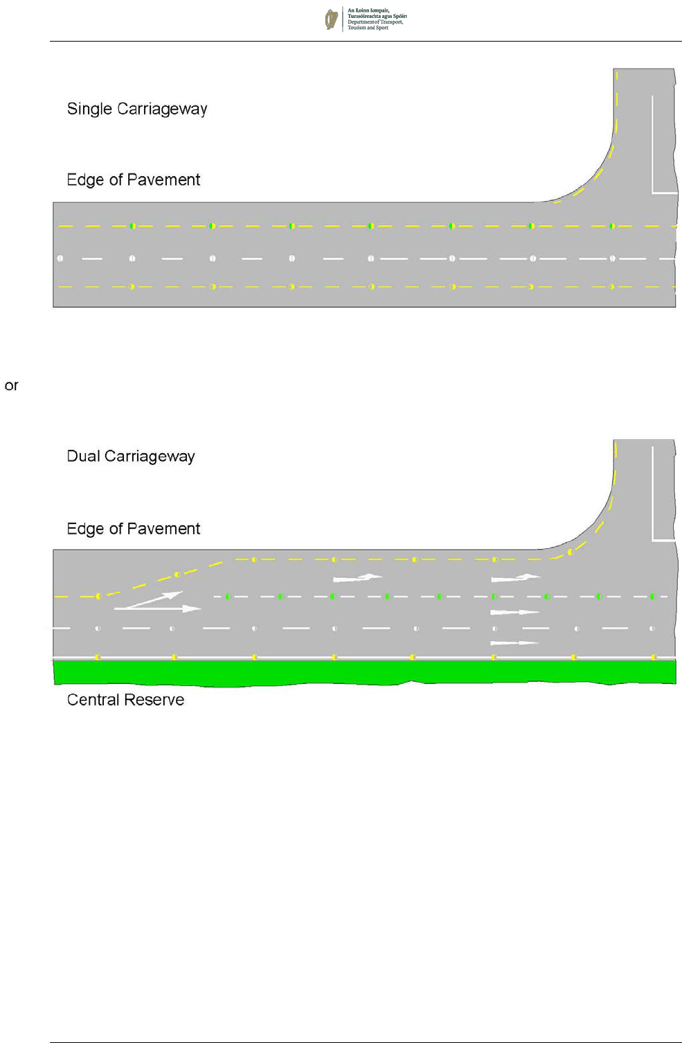
August 2019 7/78
Figure 7.38:
Permitted Edge Line Arrangements on Approach to a Junction
on an All Purpose Road
(Similar Arrangements on a Single Carriageway)
Note 1: One half of dual carriageway shown.
Note 2: All studs on a dual carriageway shall be uni-directional
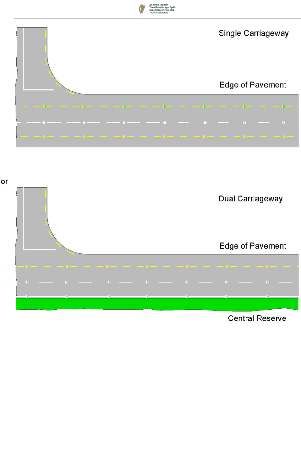
August 2019 7/79
Figure 7.39:
Permitted Edge Line Arrangements
Exiting from a Side Road onto an All-Purpose Road

August 2019 7/80
GHOST ISLAND JUNCTIONS
7.11.6 Ghost island junctions are usually provided to afford right-turning
vehicles some protection and assist free flow of major road through
traffic. Detailed guidance for the design and application of these
junctions is contained in TII Standard DN-GEO-03043. Traffic flow
warrants for the provision of ghost island junctions are provided in
the TII design standards
5
. It is important to have regard to these
warrants when considering the provision of a ghost island. A
typical layout of a ghost island junction is shown in Figure 7.40.
7.11.7 Ghost islands are normally defined by the continuous boundary
marking, which prohibits vehicles from entering the hatched area.
In circumstances where it is considered acceptable for traffic to
enter the hatched area, the broken line boundary marking may be
used (see also Section 7.4).
7.11.8 On single carriageways without hard shoulders, the road is
sometimes widened at a junction to allow nearside passing of a
right-turning vehicle. This should be delineated as shown in Figure
7.41.
RIGHT-TURN JUNCTIONS ON DUAL CARRIAGEWAYS
7.11.9 An example of the road markings required where traffic turns right
across the central reserve of a dual carriageway is shown in Figure
7.42.
5
Transport Infrastructure Ireland. TII Publications (Standards). TII, Dublin.
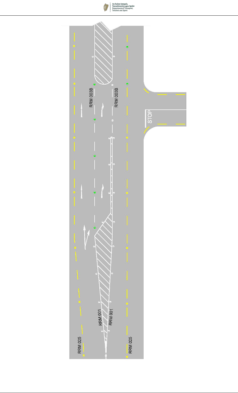
August 2019 7/81
Figure 7.40:
Single Carriageway with Ghost Island and High Volume Right Turn Traffic
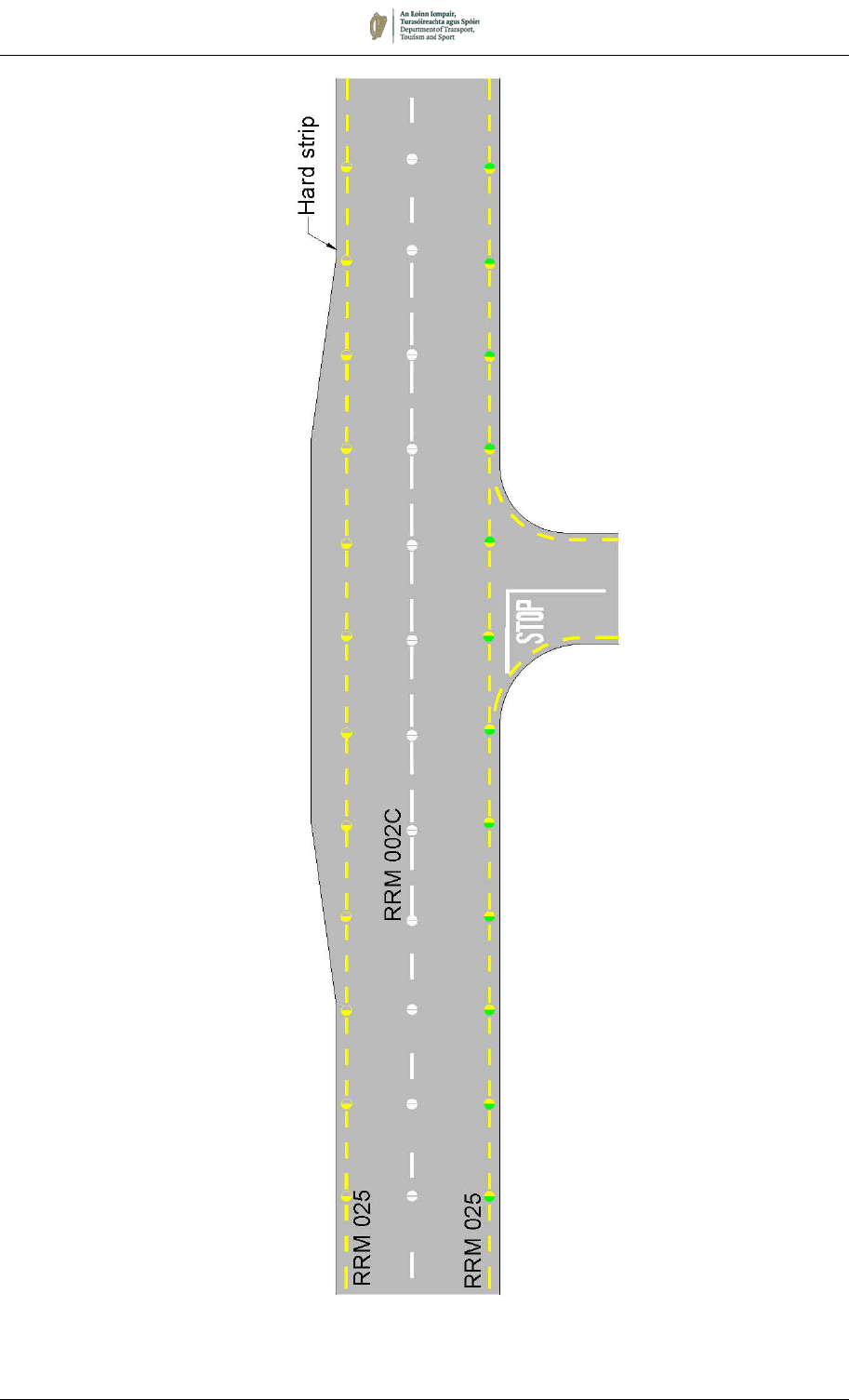
August 2019 7/82
Figure 7.41:
Single Carriageway with Low Volume Right Turn Traffic
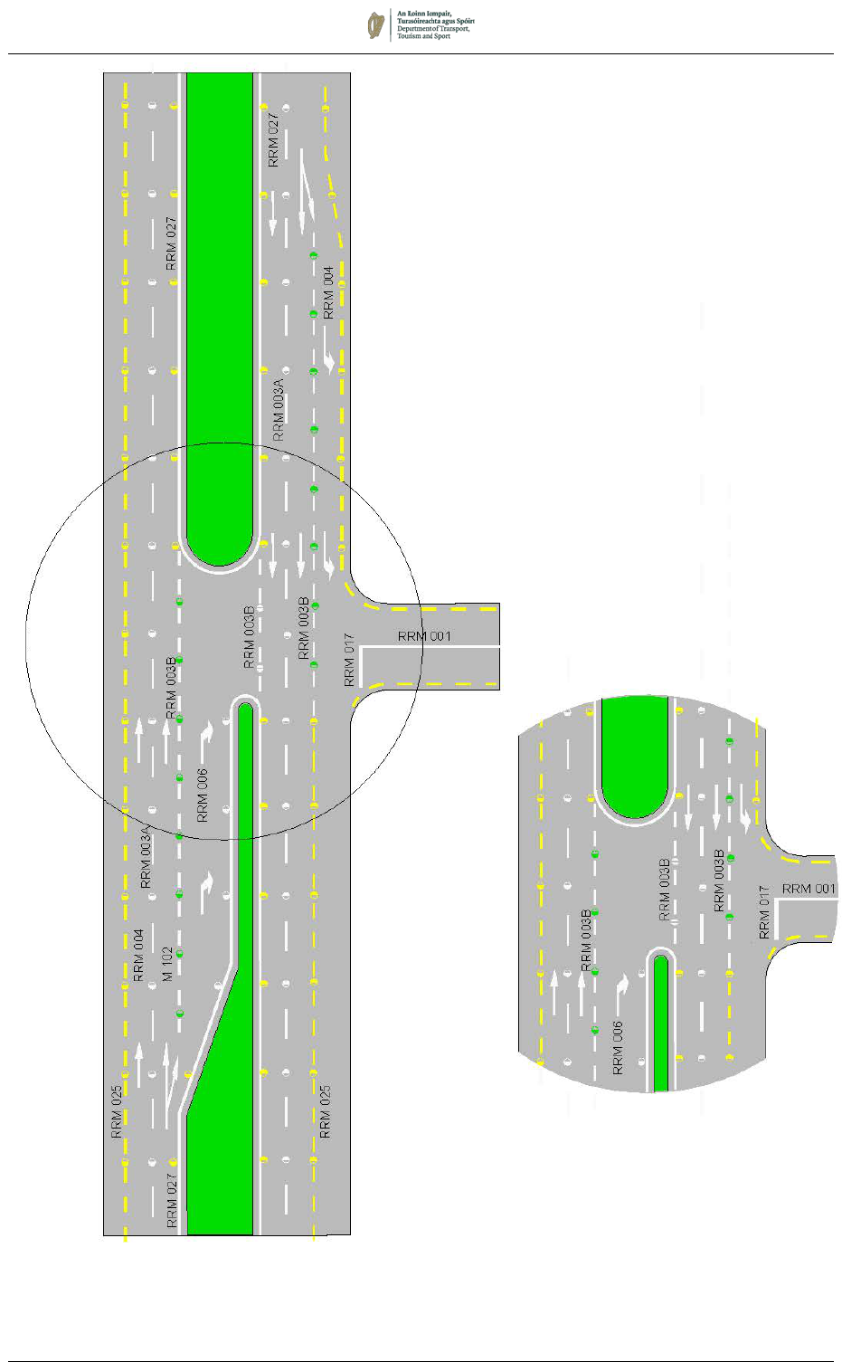
August 2019 7/83
Figure 7.42: Dual Carriageway with Right Turn Lane

August 2019 7/84
7.12 Signal Controlled Junctions
7.12.1 Adequate and proper marking of the approaches to signal-
controlled junctions is essential if the junctions are to operate at
maximum efficiency. The requirements are:
• The Stop Line must be sited as near as practicable to the
intersection, consistent with vehicle and pedestrian needs,
and drivers waiting at the Stop Line must have an
uninterrupted view of at least one traffic signal;
• Lane Lines should be arranged to secure the maximum use
of available carriageway space consistent with adequate
lane width; and
• Drivers need to be given guidance as to the correct lane to
take in good time before reaching the junction.
7.12.2 Figure 7.43 shows the standard road markings at an urban signal-
controlled junction having differing numbers of lanes on each
approach. It shows a typical arrangement of lane and centre of
carriageway markings for a six-lane road subject to a 60km/h
speed limit and a four-lane road subject to a 50km/h speed limit.
Chapter 9 contains details of the traffic signals, and an explanation
of the symbols used. Chapter 9 also includes additional sample
layouts.
Stop Line
7.12.3 The Stop Line, RRM 017, is normally located 2m in advance of the
left-hand side primary signal. It should normally be at right angles
to the centre line of the carriageway, even at skew junctions.
Advanced Cycle Stop Lines may be introduced as appropriate on
some or all of the approaches (see Section 7.2).
Lane Lines and Centre Line
7.12.4 Two patterns of Lane Lines, RRM 003, are used. The normal Lane
Lines (RRM 003A, 12 metre module) change to closer space
markings (RRM 003B, 4 metre module) on the approach to the
signals. A minimum of 5 of the closer markings should be provided
on roads subject to a speed limit of 50km/h, and 7 markings on
roads with a higher speed limit. A Continuous Centre Line, RRM
001, should be provided for at least 20m on the approach to each
Stop Line.
Pedestrian Crossings at Signals
7.12.5 Where pedestrian facilities are provided at a signal-controlled
junction, a pair of Pedestrian Lines, M 131, should be laid across
the carriageway to delineate the place for pedestrians to cross. A
Pedestrian Line consists of a continuous transverse white line
100mm wide (see Section 7.16).

August 2019 7/85
Figure 7.43:
Markings at an Urban Signal-Controlled Junction
Crossing Width
2000 - 2500
M124
RRM
004
60km/h
Speed Limit
RRM 001
RRM 003A
RRM 001
RRM 003B
(min 5 Marks)
RRM 003B
(min 7 Marks)
RRM 017
60km/h
Speed Limit
50m
25m
15m
30m
M 131

August 2019 7/86
7.13 Roundabouts
7.13.1 The most common roundabouts in general use are normal, mini
and urban roundabouts. They are defined as:
• Normal Roundabout: A roundabout having a one-way
circulatory carriageway around a kerbed central island 4m
or more in diameter and usually with flared approaches to
allow multiple vehicle entry; and
• Mini-Roundabout: A roundabout having a one-way
circulatory carriageway around a flush or slightly raised
circular marking less than 4m in diameter and with or without
flared approaches.
• Urban Roundabout (Continental style): A roundabout
having a one-way circulatory carriageway around a kerbed
central island 4m or more in diameter with single lane entry
and a single circulatory lane and tight radii. These
roundabouts are useful in controlling traffic speeds.
7.13.2 Detailed guidance for the geometric design of roundabouts is
contained in DN-GEO-03060
6
.
7.13.3 At all roundabouts, the No Entry Line, RRM 019, should be laid at
each entry and should connect the splitter island to the nearside
edge. The No Entry Line should follow approximately the line of
the inscribed circle in order to maintain visibility from each
approach lane. In general, Lane Indication Arrows should not be
used as they have legal effect and restrict flexibility of lane use for
variable traffic conditions.
7.13.4 It is important to provide adequate vehicular deflections through
the roundabout. Where raised traffic deflection islands are
provided to achieve such deflection, the vertical surfaces may be
painted in alternate black and amber bands 300mm in length to
improve their conspicuity.
NORMAL ROUNDABOUTS
7.13.5 The No Entry Line shall be used on every entry. The lines shall be
200mm wide and should be accompanied by a Triangular Yield
Markings, M 115, as described in Section 7.5. Figure 7.44 shows
the options available.
7.13.6 If an approach to the junction is divided into two or more lanes, the
Triangular Yield Marking should be placed in each lane on that
approach.
7.13.7 A single Continuous Line, RRM 001, should be provided adjacent
to the central island, approximately 300mm from the edge of
carriageway (see Figure 7.44).
6
Transport Infrastructure Ireland. DN-GEO-03060 - Geometric Design of Junctions
(priority junctions, direct accesses, roundabouts, grade separated and compact
grade separated junctions). Part of the TII Design Manual for Roads and Bridges.
NRA, Dublin.
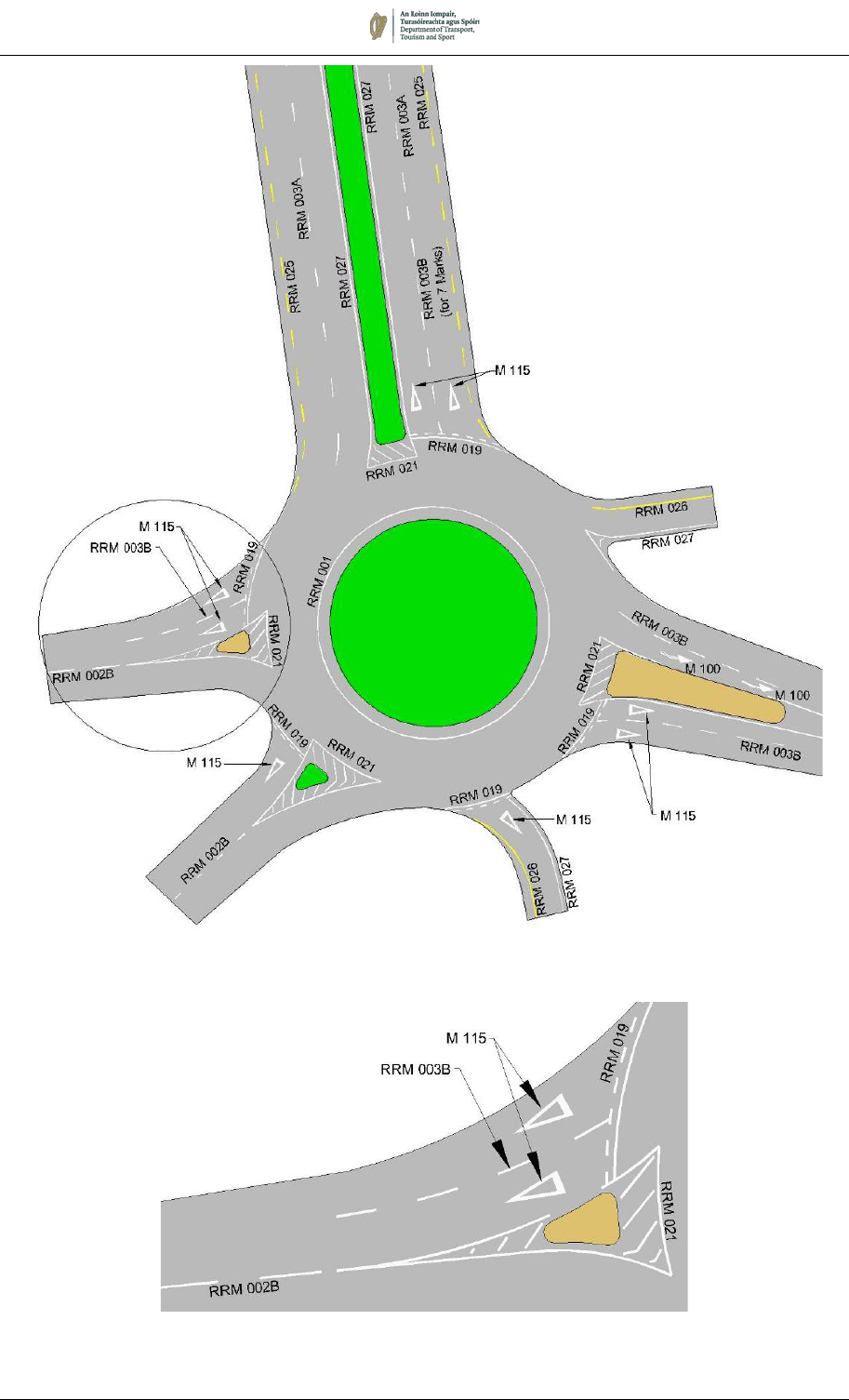
August 2019 7/87
Figure 7.44:
Markings at a Normal Roundabout
Extract from Figure 7.44:
Markings at a Roundabout Entry Arm
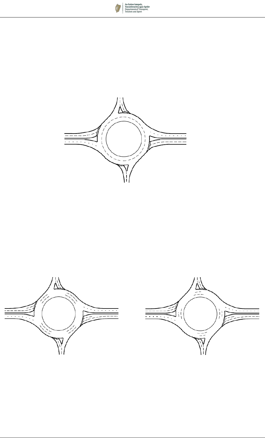
August 2019 7/88
7.13.8 Where a wide circulatory carriageway exists, provision of
circulatory markings can help to reduce driver confusion and
provide well defined paths through the junction. There are four
basic configurations of circulatory road marking:
1. Concentric markings (Figure 7.45) trace a complete path
around the circulatory carriageway, dividing it into the
number of circulating lanes that the carriageway width will
allow;
Figure 7.45: Concentric Circulatory Markings
2. Partial concentric markings (Figure 7.46) vary from
concentric in that their continuity around the circulatory
carriageway is broken, usually adjacent to the entries and/or
exits of the roundabout;
Figure 7.46: Partial Concentric Circulatory Markings
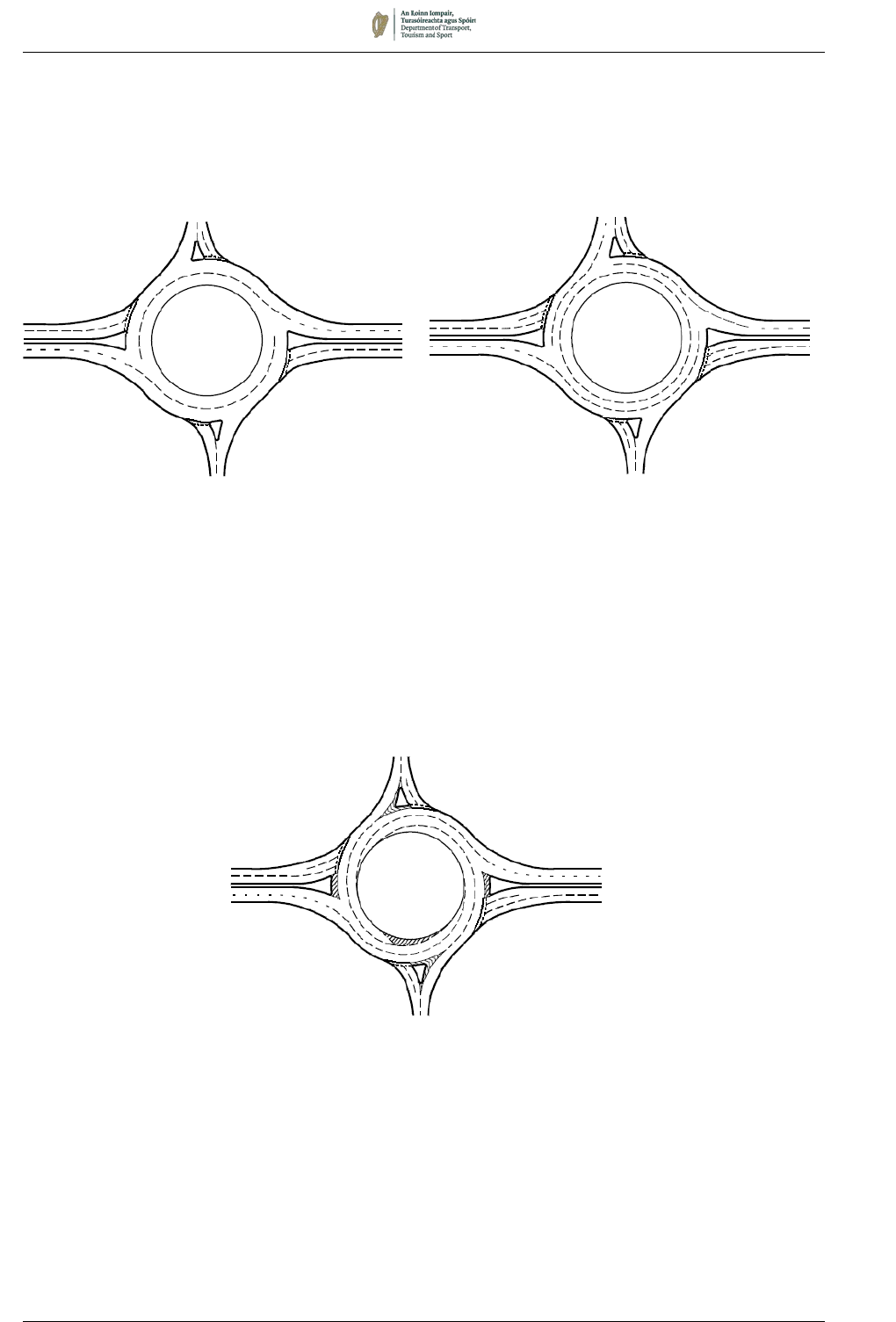
August 2019 7/89
3. Concentric spiral markings (Figure 7.47) are a hybrid. The
purpose is to direct off the outermost circulating lane or
lanes, where the exit width allows, by running the circulatory
marking smoothly into the road markings on the exit
concerned;
Figure 7.47: Concentric Spiral Circulatory Markings
4. Spiral markings (Figure 7.48) involve a series of lane gains
and lane drops around the circulatory carriageway so that
drivers enter in the lane appropriate for their desired exit and
follow the lane around the roundabout to be led off at that
exit.
Figure 7.48: Spiral Circulatory Markings
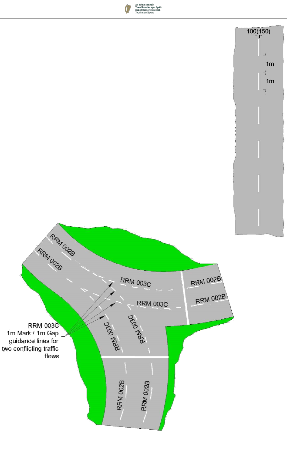
August 2019 7/90
RRM 003C:
Lane
Guidance
Line
7.13.9 The marking used to delineate lanes within the circulating
carriageway shall be the Lane Line, RRM 003B, consisting of a
100mm wide 2m segment and 2m gap.
7.13.10 In certain circumstances it may be necessary to provide lane
guidance markings for two conflicting traffic flows, for example on
the circulating carriageway of signalised roundabouts. If it is
considered that using the same marking for both traffic flows could
cause confusion, then the less dominant flow (in the case of a
signalled roundabout, the entering traffic) may be divided into
lanes using the Modified Lane Line, RRM 003C, as shown in
Figure 7.49.
7.13.11 Where hatching is provided, for example on spiral circulatory
systems, this shall have broken line boundaries (see Section 7.4).
7.13.12 Worded Lane Destination Markings, e.g. route numbers, are useful
on the approaches to roundabouts and on the circulatory
carriageway to aid lane discipline (see Section 7.5).
Figure 7.49:
Use of Lane Guidance Line, RRM 003C, on a Signalised Roundabout
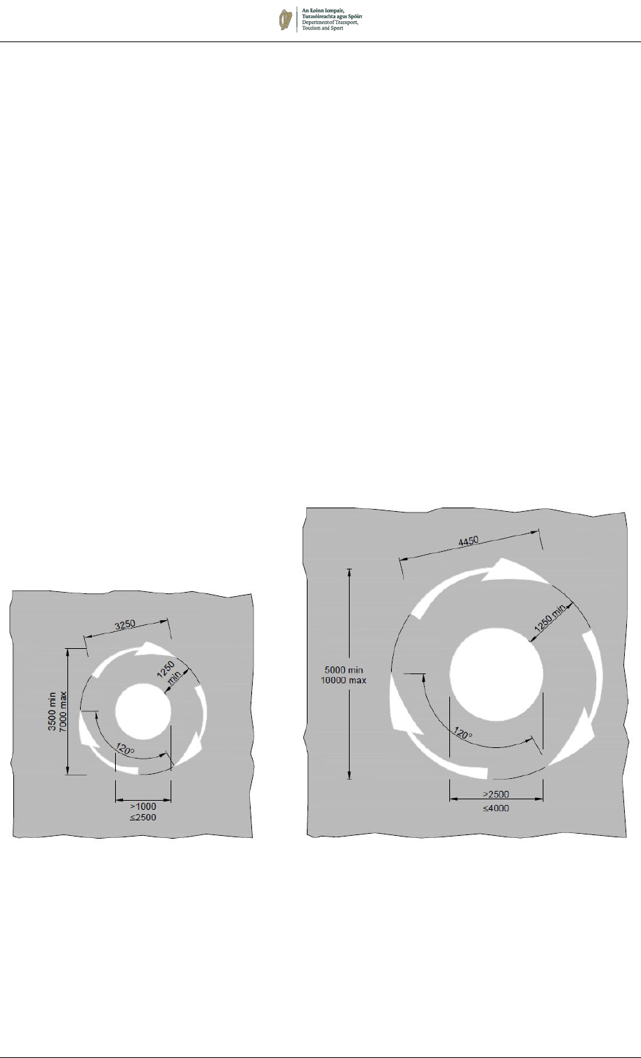
August 2019 7/91
MINI-ROUNDABOUTS, RRM 033
7.13.13 Mini-roundabouts consist of a one-way circulatory carriageway
around a flush or slightly raised central disc, between 1m and 4m
diameter, with or without flared approaches. The Mini-roundabout
Marking, RRM 033, consists of three arrows around the central
disc to indicate the direction of circulation. The central disc may
be domed up to a maximum of 125mm above the adjacent road
surface but must not exceed 6mm at the perimeter.
7.13.14 Two sizes of the Mini-roundabout Marking RRM 033 are
prescribed. The smaller, (3250mm) is used for circular central
islands up to and including 2500mm in diameter. The larger,
(4450mm) is for use with circular central islands more than
2500mm in diameter, up to including maximum of 4000mm in
diameter. The choice will depend on the road space available and
the need for conspicuity. The larger variant should be used
wherever it is needed to provide adequate deflection and deter
straight-through movement. The smaller variant may be adequate
at more constricted sites where the marking would otherwise
occupy too large a part of the carriageway space and might be
confusing, or where frequent overrunning would result in
excessive maintenance costs
RRM 033: Mini-Roundabout Markings

August 2019 7/92
7.13.15 Under no circumstances should annular rings be added around the
central disc. If a more conspicuous central marking is necessary,
a larger disc, up to a maximum of 4 m should be used. If the
junction area is very large, the diameter of the circulatory arrow
marking should be increased to a maximum of 10 m, with the
length of the arrows correspondingly increased to 4.45 m.
Conspicuity may be further enhanced by replacing the normal
central warning line on the approach with a hatched marking.
7.13.16 The central disc marking should be capable of withstanding
overrunning by large vehicles. Because of this it is not possible to
site the mandatory signs normally associated with a normal
roundabout on the central area. Chapter 5 provides information
on the relevant mandatory signs to use at a mini-roundabout.
7.13.17 The layout of a mini-roundabout should be designed so that drivers
are made aware in good time that they are approaching a
roundabout. Their conspicuity may be enhanced where necessary
by the use of warning signs (W 044) or map-type advance direction
signs. In general, mini-roundabouts should only be used when
traffic speeds on all approaches are 50km/h or less.
7.13.18 The No Entry Line, RRM 019, at mini-roundabouts is the same as
that used at normal roundabouts.
7.13.19 Road markings or small traffic islands should be placed so as to
ensure some vehicle deflection on the approaches; hatched
markings can often help. Physical islands should be kept free of
all furniture except the Keep Left bollards and other essential
signs. Where an existing junction is being converted to a mini-
roundabout, it may not be practicable to achieve the ideal amount
of deflection. However, this may be acceptable if approach speeds
are low.
7.13.20 Where suitable deflection cannot be achieved, traffic entering the
roundabout might, because of its approach speed, disregard the
Yield requirement of the No Entry Line. In such cases, the Yield
Sign (RUS 026) may be mounted on the same post and above the
Mini-roundabout sign (RUS 049).
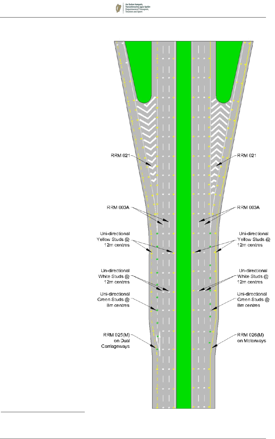
August 2019 7/93
7.14 Grade-Separated Junctions
7.14.1 Grade-separated
junctions may involve
merging and diverging
lanes, the gain or loss of
lanes, or a combination
of these. As junctions
become more complex,
so road marking layouts
become more
complicated. It is
therefore not possible to
detail all possibilities,
but the standard
principles should be
followed. Reference
should be made to
Standard DN-GEO-
03035
7
for further
guidance. When
designing a complex
junction, it should be
borne in mind that it
must be capable of
being signed and
marked in a way that
drivers can readily
understand.
7.14.2 The layout of markings
at the simplest grade-
separated junction is
shown in Figure 7.50.
Comprehensive details
of the longitudinal
markings and stud
spacings are given in
Sections 7.3 and 7.10.
This arrangement is
suitable for one or two-
lane exit slip roads and
one-lane entry slip
roads.
7
Transport Infrastructure Ireland. DN-GEO-03035 Layout of Grade Separated
Junctions. TII Dublin.
Figure 7.50: Entry and Exit Slip Roads
(Dual Three Lane Carriageways)

August 2019 7/94
7.15 Level Crossings
7.15.1 The markings associated with a railway level crossing are shown
in Figure 7.51. The markings comprise:
1. Yellow Box Marking, RRM 020, indicating the area to be
kept clear of stationary traffic. Note that at railway level
crossings the boundary lines shall be 300mm wide; the
diagonal lines shall be 200mm wide and 1400mm apart, and
set at an angle of 60º relative to each other, irrespective of
the geometry of the boundary lines;
2. Transverse vehicle Stop Line, RRM 017. A special line
width of 300mm shall be used, which must be at right angles
to the direction of vehicular travel. Where the approach
carriageway width is insufficient for centre line markings, the
Stop Line shall extend across the full width of the road on
both sides of the crossing;
3. Transverse Exit Boundary Line, M 122, indicating the extent
of the crossing on the exit side. This line shall be 300mm
wide with 900mm marks and 450mm gaps;
4. Approach carriageway continuous Centre Line, RRM 001,
extending back at least 20m from the Stop Line, but this may
be reduced to a minimum of 8m as site conditions require.
On roads less than 5.3m width only, the centre line marking
may be reduced to 2m;
5. Internal carriageway centre Warning Line, RRM 002D,
extending between the two vehicle Stop Lines. This
marking may only be omitted in cases where the
carriageway width across the level crossing is less than
5.3m;
6. Edge of Carriageway Markings, RRM 025, shall be laid
between the two vehicle Stop Lines, to define the edge of
the vehicle running lanes through the level crossing. They
may also serve to indicate the segregation of pedestrian and
vehicle paths, as it is not possible to maintain a level
difference between footway and carriageway through the
crossing; and
7. If appropriate, a Back of Footway Line, M 123, may be used
to designate the back of the pedestrian footway through the
level crossing. This is a 100mm wide continuous white
marking.
7.15.2 The example shown in Figure 7.51 illustrates a simple level
crossing with a single railway line. In the case of multiple lines or
an acute crossing angle, the box marking may be extended as
shown in Figure 7.52.
7.15.3 The warning signs associated with level crossings are described
in Chapter 6 and the signals in Chapter 9.
7.15.4 Road studs shall be provided for Centre Line and Edge of
Carriageway Markings as prescribed in Section 7.10, but any stud
laid within 2m of a running rail shall be of plastic construction.
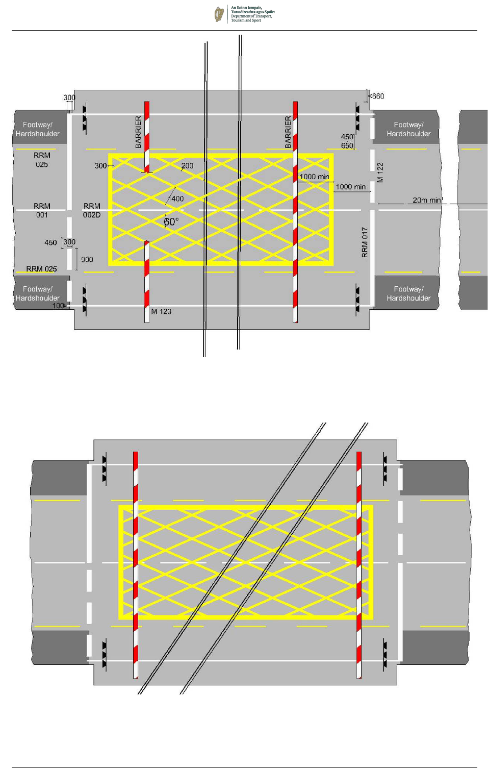
August 2019 7/95
Figure 7.51:
Markings at a Level Crossing
Figure 7.52:
Extended Yellow Box Marking at a Level Crossing
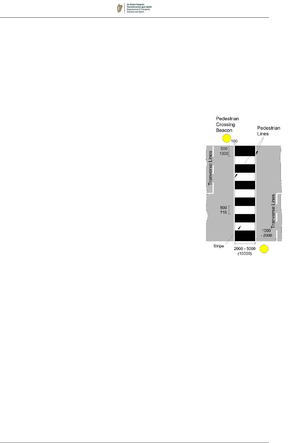
August 2019 7/96
7.16 Pedestrian Crossings
7.16.1 A series of road markings is prescribed to delineate Zebra or
Signalised Pedestrian Crossings. Additional Zigzag Markings are
available to define ‘controlled areas’ adjacent to the crossings.
ZEBRA CROSSING (RPC 001)
7.16.2 A set of Pedestrian Lines, Transverse Lines, Stripes, and
Pedestrian Crossing Beacons together form a Zebra Crossing,
RPC 001. These markings are laid out as follows:
7.16.3 Pedestrian Lines: Pedestrian lines indicate the limits of the
pedestrian crossing area. They consist of two lines across the
carriageway at a minimum distance of 2.0m apart (normally 2.4m
apart). The lines are white, continuous and 100mm wide.
7.16.4 The width of a pedestrian crossing may be dictated by site
conditions. However, where space permits the width of 2.0m
should be increased by an additional 500mm for every 125
pedestrians per hour above 600, averaged over four peak hours,
up to a maximum of 5m or, in exceptional circumstances, 10m.
7.16.5 The Transverse Line consists of a single white broken line
comprising 500mm segment and 500mm gaps. The marks are
200mm wide. This line is normally sited 1m to 2m from and parallel
to the Pedestrian Line used to indicate the limits of the crossing
and should extend across the approach lanes.
7.16.6 Stripes: The stripes should be laid in an alternate black and white
pattern across the full width of the carriageway and positioned
centrally between the two Pedestrian Lines.
7.16.7 The stripe immediately adjacent to the kerb on both sides of the
road should be black and should not be less than 500mm nor more
than 1300mm wide. The intermediate black and white stripes
should be not less than 500mm nor more than 715mm wide and
should normally be of equal width.
7.16.8 If the road surface is dark (e.g. bituminous macadam) between the
pedestrian lines, then the surface colour itself will be sufficient to
constitute the ‘black’ stripes. However, with the increasing use of
high skid-resistant surfacing in a variety of light colours, care must
be exercised to ensure that there is sufficient visual contrast
between alternating stripes to indicate clearly the presence of the
crossing.
7.16.9 The prescribed Zebra Crossing must include Pedestrian Crossing
Beacons, located on either side of the road (and on a refuge where
provided), on the side of the stripes from which traffic approaches.
For details of the beacons, see Chapter 9.
RPC 001:
Zebra Crossing
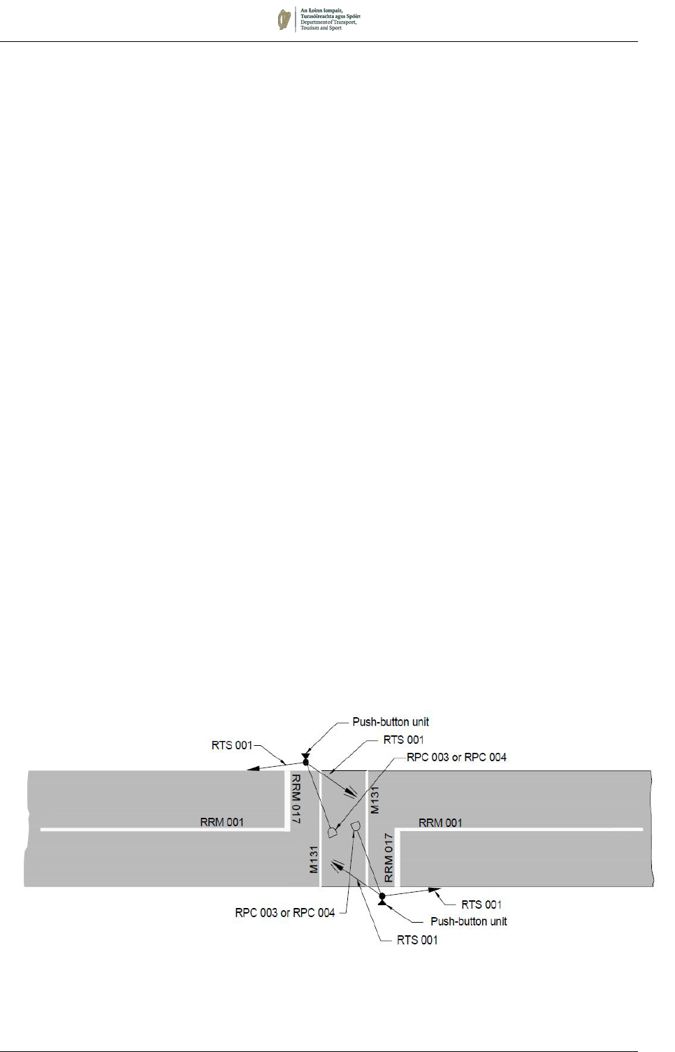
August 2019 7/97
SIGNALISED PEDESTRIAN CROSSING
7.16.10 Pedestrian crossings may also be controlled by pedestrian-
operated traffic signals (RPC 003 or RPC 004), as described in
Chapter 9. These may be Pelican Crossings or conventional
signalised pedestrian crossings. Toucan Crossings provide a
combined signalled crossing facility for pedestrians and cyclists.
The markings for all these are identical.
7.16.11 The carriageway markings used to indicate a signalised pedestrian
crossing are as follows:
7.16.12 Pedestrian Lines, M 131, between 2000mm and 5000mm apart,
as described for Zebra Crossings, to indicate the limits of the
crossing. In exceptional circumstance, where very large
pedestrian flows occur, the width may be increased to a maximum
of 10m.
7.16.13 Stop Lines, RRM 017, to indicate where traffic should stop when
signalled to do so (see Section 7.2).
7.16.14 Where the road carries two-way traffic and the crossing is
uninterrupted, the Stop Line should extend from the edge to the
centre of the carriageway, parallel to the Pedestrian Line, and
placed not less than 1.0m or more than 5m from the Pedestrian
Line (normally 2.0m).
7.16.15 On a one-way street where the crossing is uninterrupted, the Stop
Line should extend from one edge of the carriageway to the other
edge, positioned as above.
7.16.16 On a two-way road the Stop Line should always be accompanied
by a Continuous Centre Line, RRM 001, extending longitudinally
back from the junction (see Section 7.2).
7.16.17 Where the crossing caters for cyclists as well as pedestrians, the
same signals and road markings are used, together with Cyclist
Signals RTS 006 and RTS 007 (see Chapter 9).
Figure 7.53:
Signalised Pedestrian Crossing
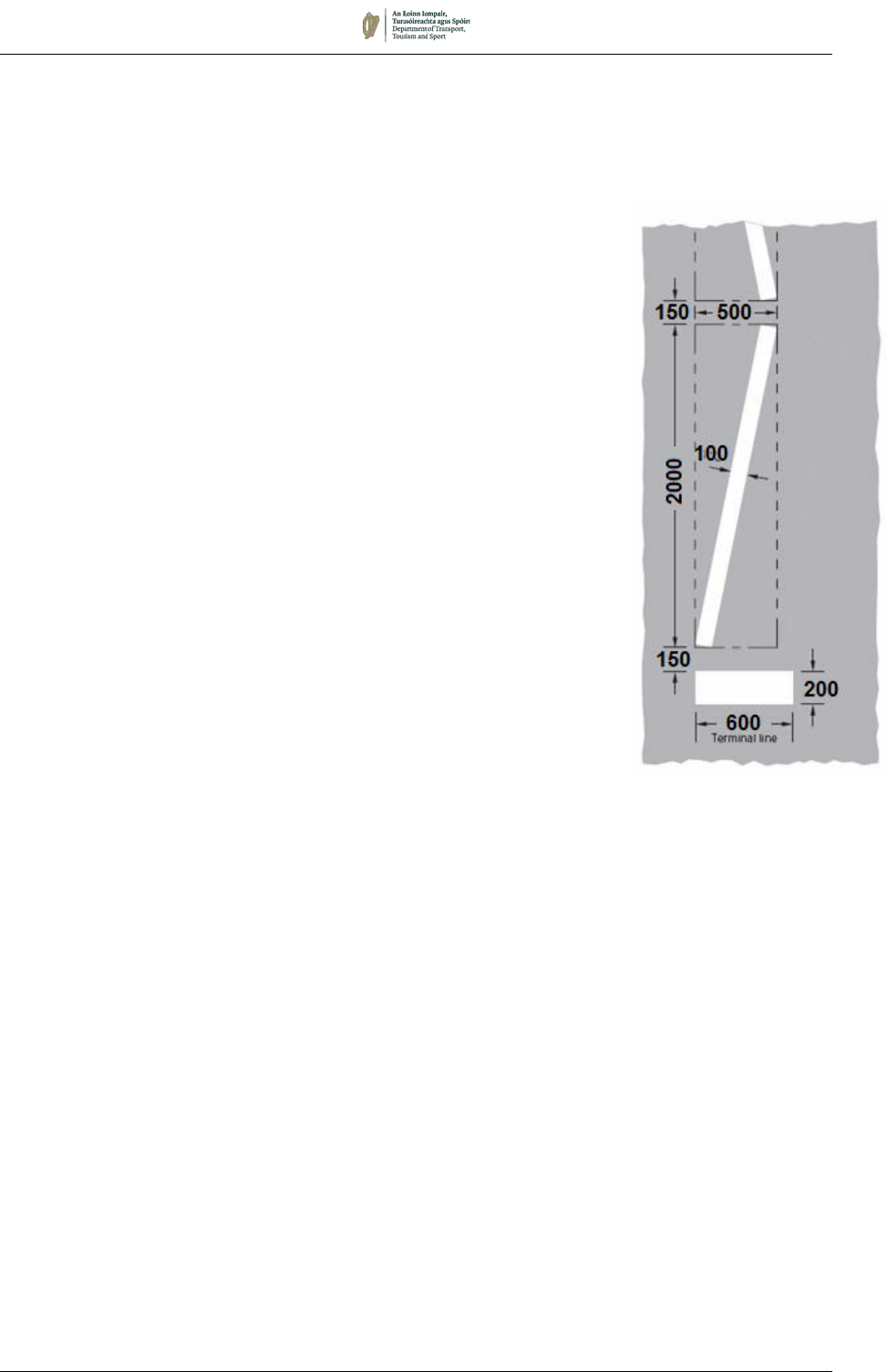
August 2019 7/98
RPC 002:
Zigzag and Terminal
Line
ZIG-ZAG MARKINGS (RPC 002)
7.16.18 Both Zebra Crossings and Signalised Pedestrian Crossings may
be accompanied by Zigzag Markings and Terminal Lines (RPC
002) along the edge of carriageway before and after the crossing.
Zigzag Markings serve the dual purpose of indicating that part of
the road (the ‘controlled area’) where vehicles are not permitted to
park in the vicinity of a pedestrian crossing and providing visual
warning to drivers of the location of a crossing.
7.16.19 The length of each zigzag mark is 2m measured parallel to the
adjacent kerb.
7.16.20 The “standard” controlled area is designated by eight 2m zigzag
marks laid adjacent to the nearside kerb on the approach to a
crossing, and a minimum of three zigzag marks adjacent to the
kerb on the exit to the crossing; this may be extended as required
by site conditions. A gap of 200mm to 250mm should be left
between the kerb and the nearest part of the Zigzag Markings.
Where a longer approach warning is required, e.g. due to poor
visibility or speed of traffic, the number of zigzag marks may be
increased to a maximum of eighteen. Where the siting of a
crossing makes it impracticable to provide eight zigzag marks on
the approach, the number may be reduced to a minimum of three
marks. At the end of the Zigzags Markings remote from the
crossing, a transverse Terminal Line, 600mm long by 200mm
wide, shall be provided.
7.16.21 Within the ‘controlled area’ of a Zebra Crossing, pedestrians are
prohibited from crossing the roadway other than on the pedestrian
crossing, and the parking of vehicles is restricted. Together with
the markings to indicate a Pedestrian Crossing, RPC 001, the
Zigzag Markings and Terminal Lines, RPC 002, indicate the extent
of the controlled area (see Figure 7.54).
7.16.22 Zigzag Markings and Terminal Lines shall be provided on each
side of the carriageway, on the approaches and departures, to
create the ‘controlled area’.
7.16.23 On carriageways greater than 6.2m wide a third Zigzag Marking
shall be laid along the centre of the road for the same length as
the longer of the two edge Zigzag Markings. Where there is a
pedestrian refuge, a double row of Zigzag Markings should be laid,
one either side of the refuge.
7.16.24 Where traffic approaches or leaves the crossing in two or more
lanes, the lanes shall be segregated with Lane Lines, RRM 003B,
100mm wide, with 2m marks and 2m gaps for the length of the
controlled area.
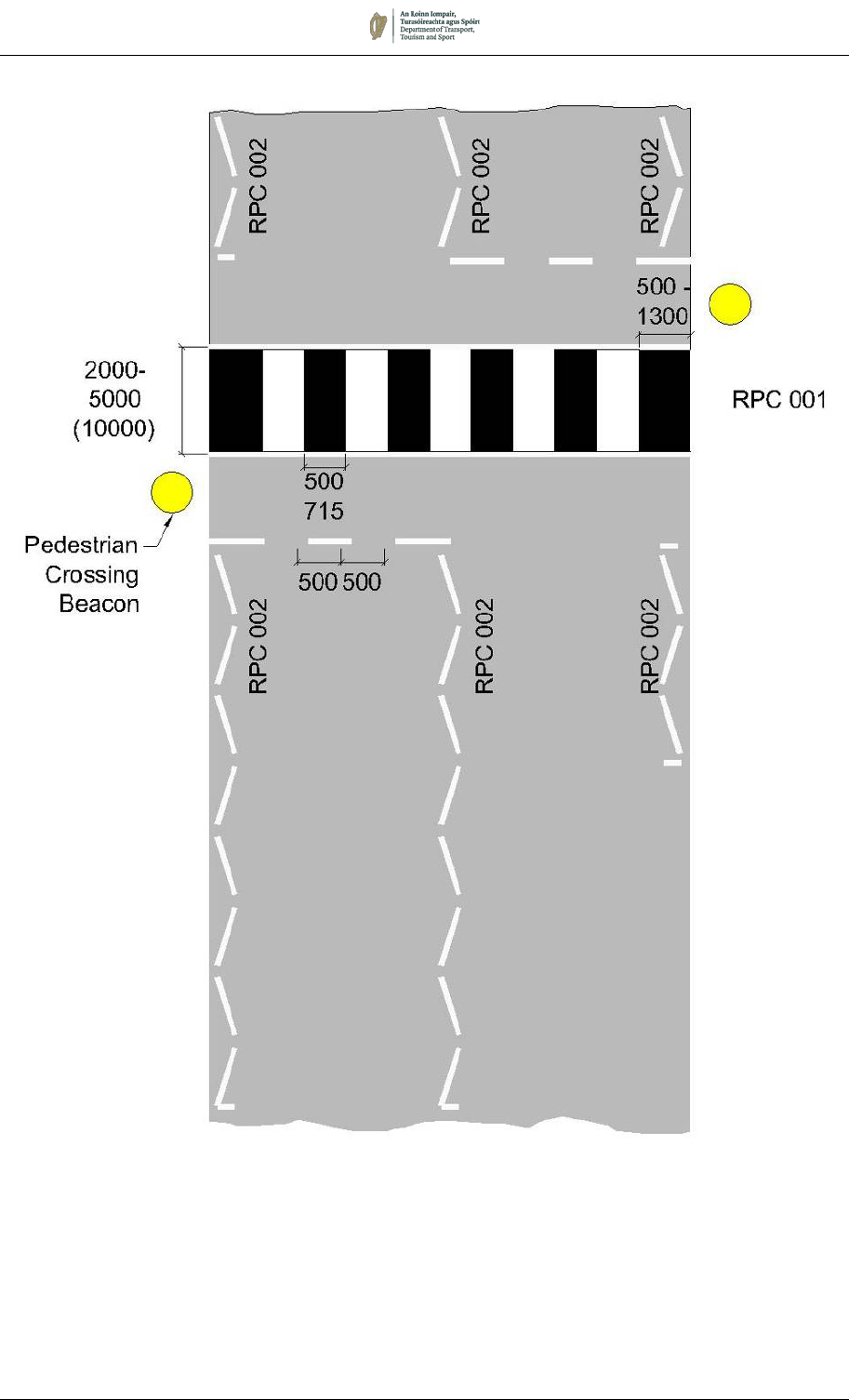
August 2019 7/99
Figure 7.54:
Zebra Pedestrian Crossing with RPC002
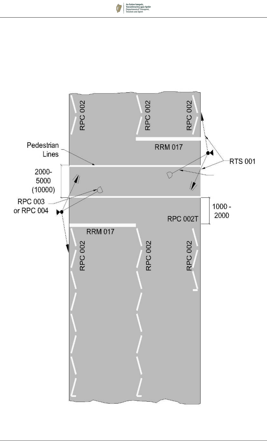
August 2019 7/100
7.16.25 Zigzag Markings and Terminal Lines, RPC 002, may also be used
to define a controlled area adjacent to a Signalised Pedestrian
Crossing. The requirements are the same as for these markings
adjacent to a Zebra Crossing (see Figure 7.55).
Figure 7.55:
Signalised Pedestrian Crossing with RPC 002
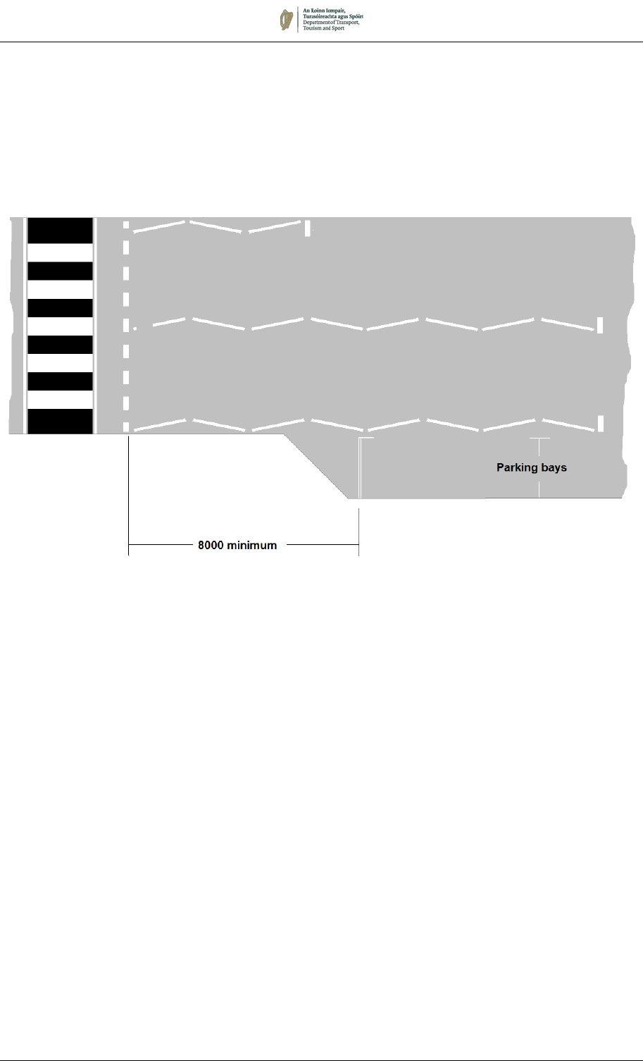
August 2019 7/101
7.16.26 In cases where a build-out has been provided to enhance
pedestrian visibility, or alternatively where a lay-by exists or can
be constructed, it is acceptable to permit parking or loading
between the edge Zigzag marking and the kerb. However, such
bays shall be no closer than 8m from the crossing. Figure 7.56
shows a typical layout with a build-out on the approach to a Zebra
Crossing.
Figure 7.56:
Parking on the Approach to a Zebra Crossing with Build-out
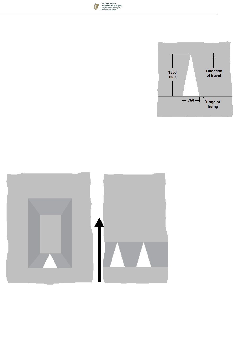
August 2019 7/102
M 112
Traffic Calming Triangle
7.17 Traffic Calming
7.17.1 The Traffic Calming Triangle, M 112, is used on the approach side
of vertical traffic calming features. It should extend from the
leading edge of the hump or cushion to the highest point (or for a
maximum distance of 1850mm). Figure 7.57 illustrates its
application in specific circumstances.
7.17.2 At speed cushions, a single M 112 marking should be used on the
approach ramp. Where vehicles from both directions might be
driven over the same cushion, the triangular marking should be
used on both approach ramps.
7.17.3 At road humps, the marking M 112 should extend for the length of
the ramp, or for a maximum distance of 1850mm. Two triangular
marks should be used in each lane; in one-way roads they should
be placed only on the approach side of a road hump.
7.17.4 Except on roads with a 30km/h speed limit, lengths of road with
road humps should be provided with Road Hump warning signs,
W 130, at either end (see Chapter 6).
Figure 7.57:
Traffic Calming Triangle on Speed Cushion and Speed Hump
Direction of travel
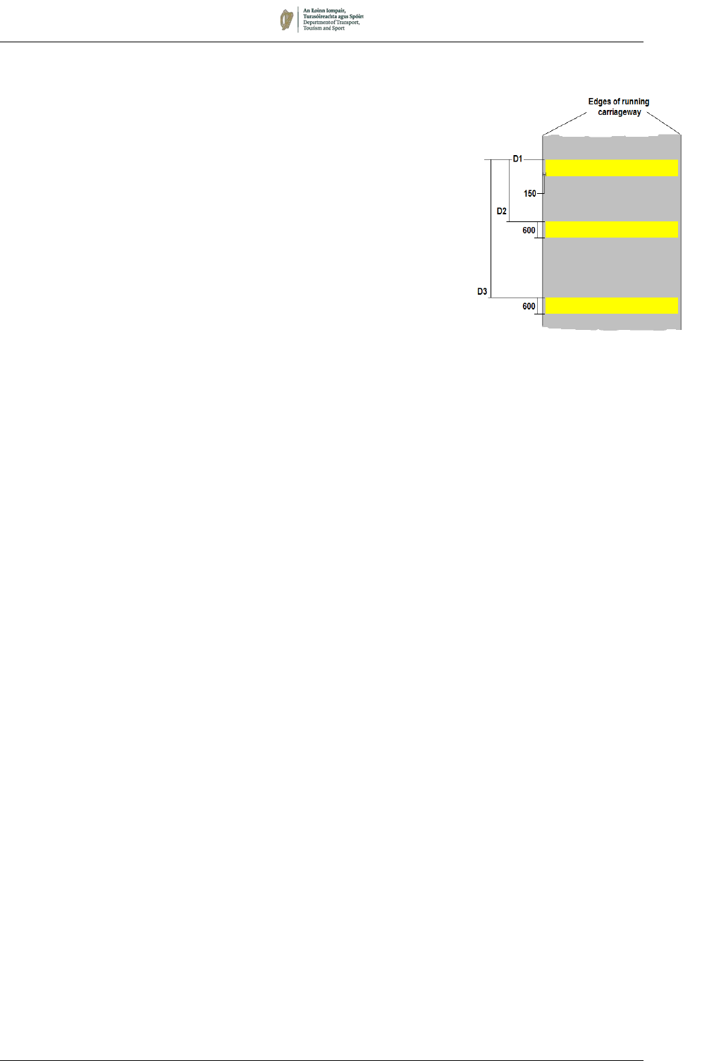
August 2019 7/103
M 113:
Yellow Bar Markings
7.18 Yellow Bar Markings
7.18.1 Yellow Bar Markings, M 113, are used in certain conditions on
high speed approaches to roundabouts, either on the main
carriageway or on an exit slip road. They have been shown to
be effective in reducing collisions associated with speed
adaptation, i.e. where drivers have been travelling at sustained
high speed for long periods. The types of collisions most likely
to be influenced are single vehicle and overrun collisions.
7.18.2 Yellow Bar Markings should not be used in an attempt to reduce
speeds at sharp bends or other hazards. They are not normally
appropriate on slip roads if there is a segregated left-turn lane for
the roundabout, or at roundabouts controlled by traffic signals.
On approaching a green signal, some drivers will slow down in
response to the markings, while others will maintain speed in an
attempt to beat a change to red. Markings are unlikely to be
appropriate in such cases unless the collision justification is
strong.
7.18.3 Before use of Yellow Bar Markings is contemplated, it is essential
to ensure that all standard signing has been correctly installed.
The warning signs described in Chapter 6 should be provided
and be of the appropriate sizes. All signs should be checked to
ensure they are in good condition, not obscured, e.g. by
vegetation, and are sited at the correct distances from the
junction. Only then should treatment with Yellow Bar Markings
be considered.
7.18.4 Yellow Bar Markings should only be used where the following
criteria are satisfied:
• The carriageway on which they are to be laid is a one-way
approach to a roundabout (i.e. a dual carriageway or an exit
slip road);
• There is at least 3km of dual carriageway in advance of the
site, with no major intersections or curves with a horizontal
radius less than the desirable minimum for a 100km/h
design speed (see DN-GEO-03031);
• The road is subject to a speed limit of 100km/h or 120km/h;
and
• The collision record for the roundabout includes at least
three collisions involving personal injury during the
preceding three years, in which speed on the relevant
approach was a contributory factor.
7.18.5 Each approach to a given roundabout shall be treated as a
separate site and the use of the markings on each approach
should be justified independently. The application of the criteria
in the previous paragraph will ensure that the markings are used
only at sites where they are likely to make a positive contribution
to safety.
7.18.6 Yellow Bar Markings consists of a series of yellow transverse
bars across the carriageway. The bars are 600mm wide and are
laid at right angles to the centre line of the carriageway. The bar
closest to the roundabout (D1) is laid at a distance of 50m,
measured along the centre line of the carriageway, in advance
of the No Entry Line. Successive bars are spaced in accordance
August 2019 7/104
with the running measurements given in Table 7.7. The 45
marks spaced as specified are designed to reduce the approach
speed of traffic from an entry speed of 120km/h at D45 to about
40km/h at D1 (i.e. 50m from the No Entry Line) and extend for
an overall distance of 200m (see Figure 7.58).
7.18.7 To assist surface water drainage, each end of each bar should
be terminated about 150mm from the edge of the carriageway or
the Edge of Carriageway Line if provided. This may be increased
to 750mm where there is a particular drainage problem, or if
there are significant numbers of cyclists. Bars should not be
extended across hard strips or hard shoulders as this would give
the impression that these are traffic lanes.
7.18.8 The bars should not exceed 5mm in thickness, and the combined
thickness of the bars and any superimposed marking must not
exceed 6mm. Although thinner markings might need more
frequent renewal, they are less likely to result in noise levels
which would be unacceptable to local residents. Drop-on glass
beads should not be applied.
Table 7.7: Spacing of Yellow Bar Markings
Bar No.
Distance
from D1
(m)
Bar No.
Distance
from D1
(m)
Bar No.
Distance
from D1
(m)
D1
0.00
D16
47.60
D31
112.85
D2
2.55
D17
51.25
D32
118.00
D3
5.35
D18
55.00
D33
123.30
D4
8.20
D19
58.85
D34
128.70
D5
11.15
D20
62.80
D35
134.20
D6
14.20
D21
66.85
D36
139.80
D7
17.30
D22
71.00
D37
145.50
D8
20.45
D23
75.25
D38
151.35
D9
23.65
D24
79.60
D39
157.35
D10
26.90
D25
84.05
D40
163.55
D11
30.20
D26
88.60
D41
170.00
D12
33.55
D27
93.25
D42
176.70
D13
36.95
D28
98.00
D43
183.90
D14
40.45
D29
102.85
D44
191.60
D15
44.00
D30
107.80
D45
200.00
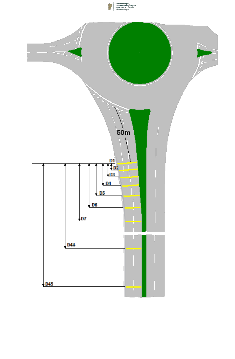
August 2019 7/105
Figure 7.58:
Yellow Bar Markings on Approach to Roundabout
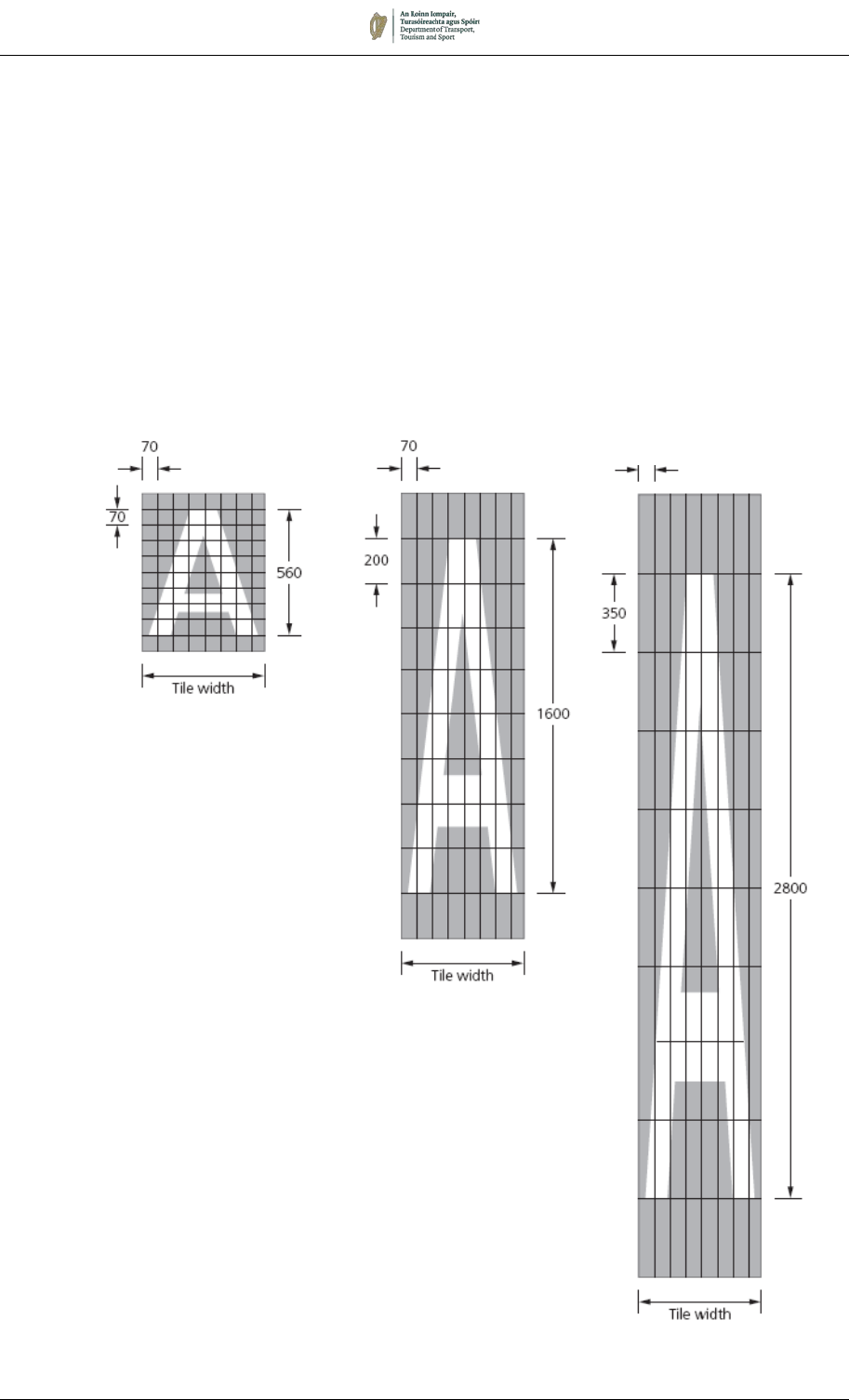
August 2019 7/106
Appendix 7A: Lettering for Worded Markings
7A.1 The characters used for worded road markings are the capital
letters, numerals, ampersand (&), forward slash (/), apostrophe
and fada from the Transport Medium alphabet. The base font is
shown in Figure 7.60 with an x-height of 400mm (capital letter
height 560mm), although it may be scaled as necessary for
specific letter heights (e.g. 300mm capital letter height for
’LOADING’ in RRM 009).
7A.2 To produce the elongated fonts as specified in a number of
markings (e.g. ‘STOP’, M 114), the 400mm x-height base font is
stretched vertically by ratios of 200/70 and 350/70 (see Figure
7.59) to produce capital letters of 1600 and 2800mm as required.
The elongated fonts are shown in Figures 7.61 and 7.62.
Figure 7.59:
Construction of Elongated Text
(Based on Transport Medium)

August 2019 7/107
7A.3 To ensure correct letter spacing when forming a word, the
characters are placed on imaginary tiles which vary in width
according to the size of the character and the tiles butted up to
each other to make the legend. The tile width for each letter is
shown in Table 7.8 and will be the same for both the elongated
letter heights and for the 560mm high base font. The distance
between the tiles of separate words when marked on a single line
is 400 mm, measured to the edge of the tiles and not to the actual
characters.
Table 7.8: Character Tile Widths
7A.4 The fada accent (shown inset above the letter ‘A’ in each of the
following figures) can apply to any vowel and should be ignored
when spacing words vertically. It will therefore have no effect on
either the tile width or height of the corresponding letter.
Letter
Width
(mm)
Letter
Width
(mm)
Letter
Width
(mm)
A 544 N 672 1 316
B 588 O 624 2 480
C 592 P 520 3 508
D 616 Q 632 4 528
E 528 R 564 5 488
F 476 S 548 6 504
G 620 T 436 7 416
H 640 U 616 8 520
I 292 V 520 9 512
J 372 W 732 0 532
K 552 X 512 ’ 156
L 428 Y 492 & 504
M 736 Z 476 / 420
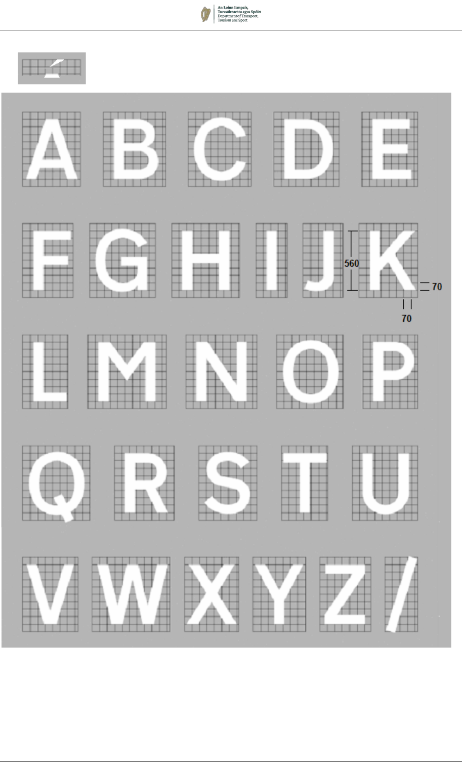
August 2019 7/108
Figure 7.60:
Transport Medium Base Font
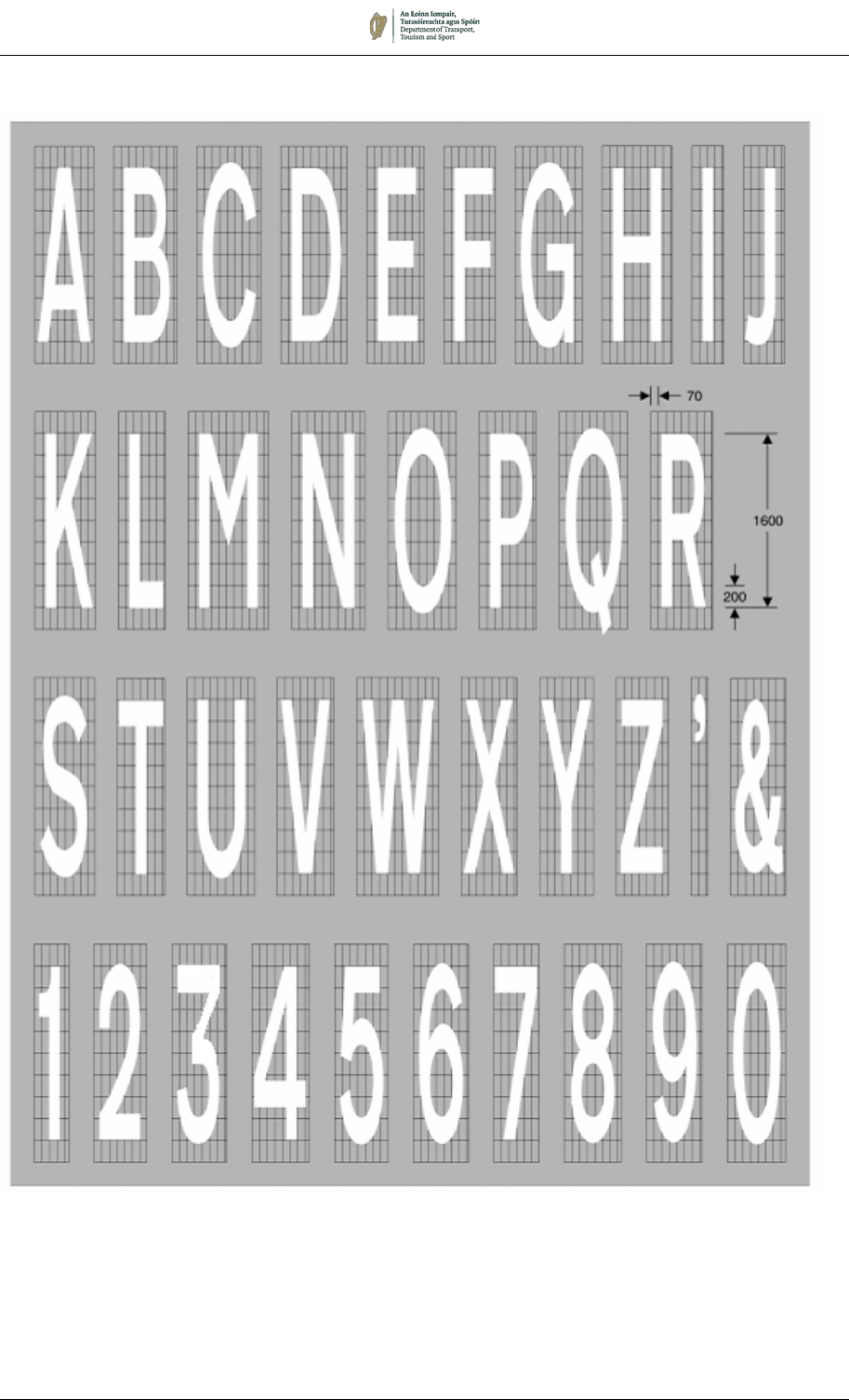
August 2019 7/109
Figure 7.61:
1600mm Elongated Font
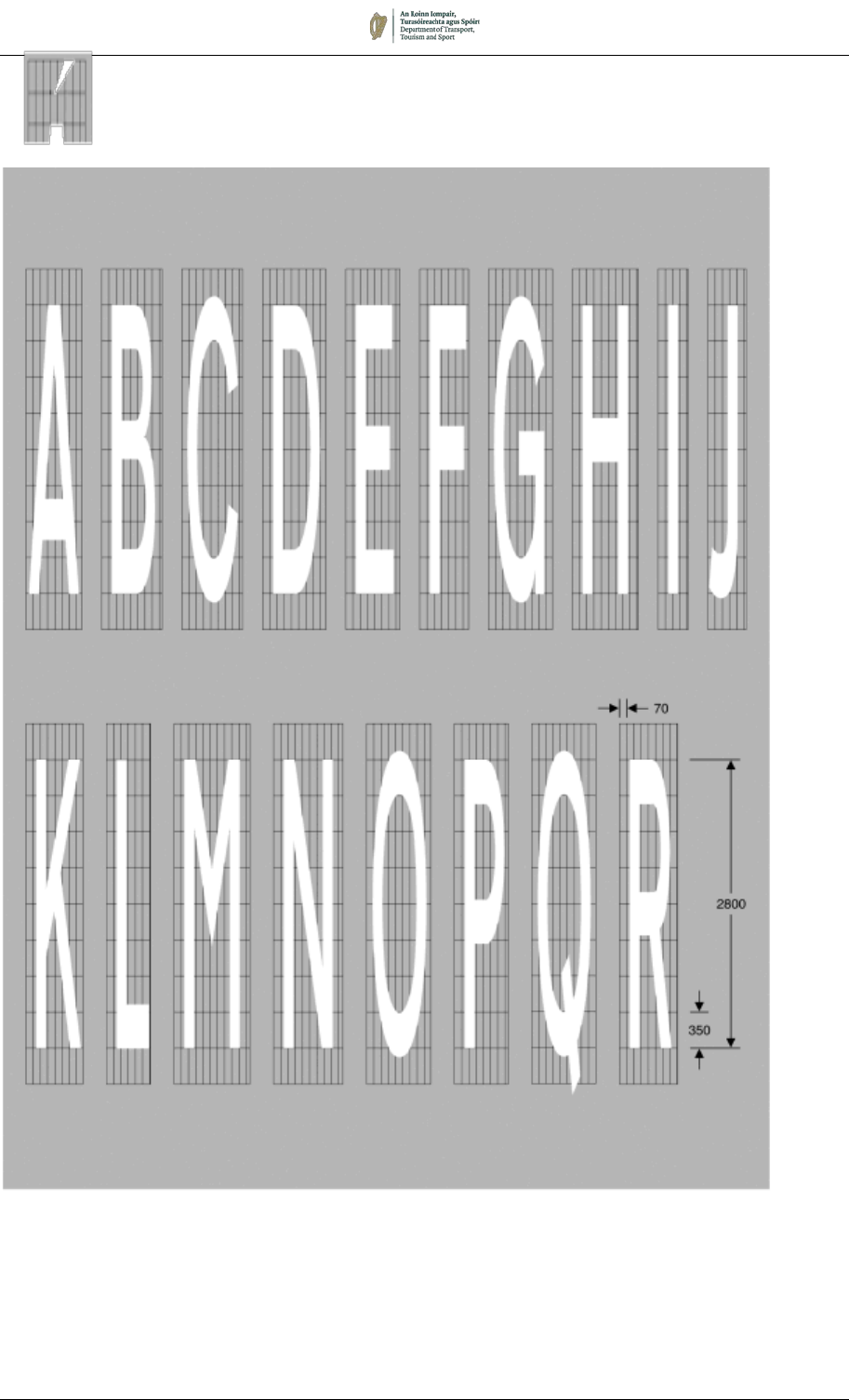
August 2019 7/110
Figure 7.62:
2800mm Elongated Font
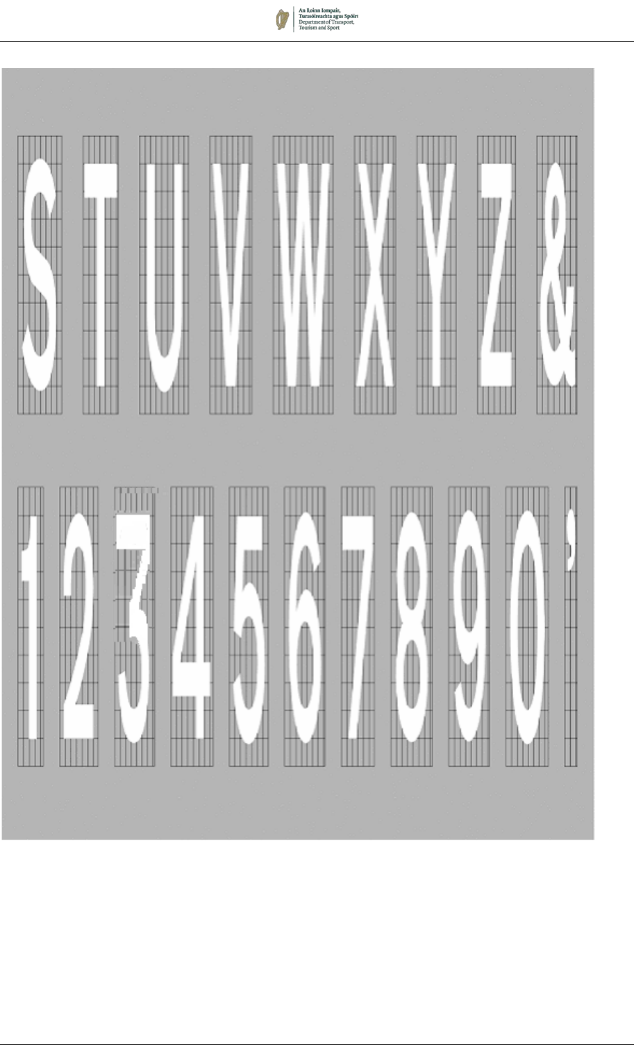
August 2019 7/111
Figure 7.62:
2800mm Elongated Font (Continued)
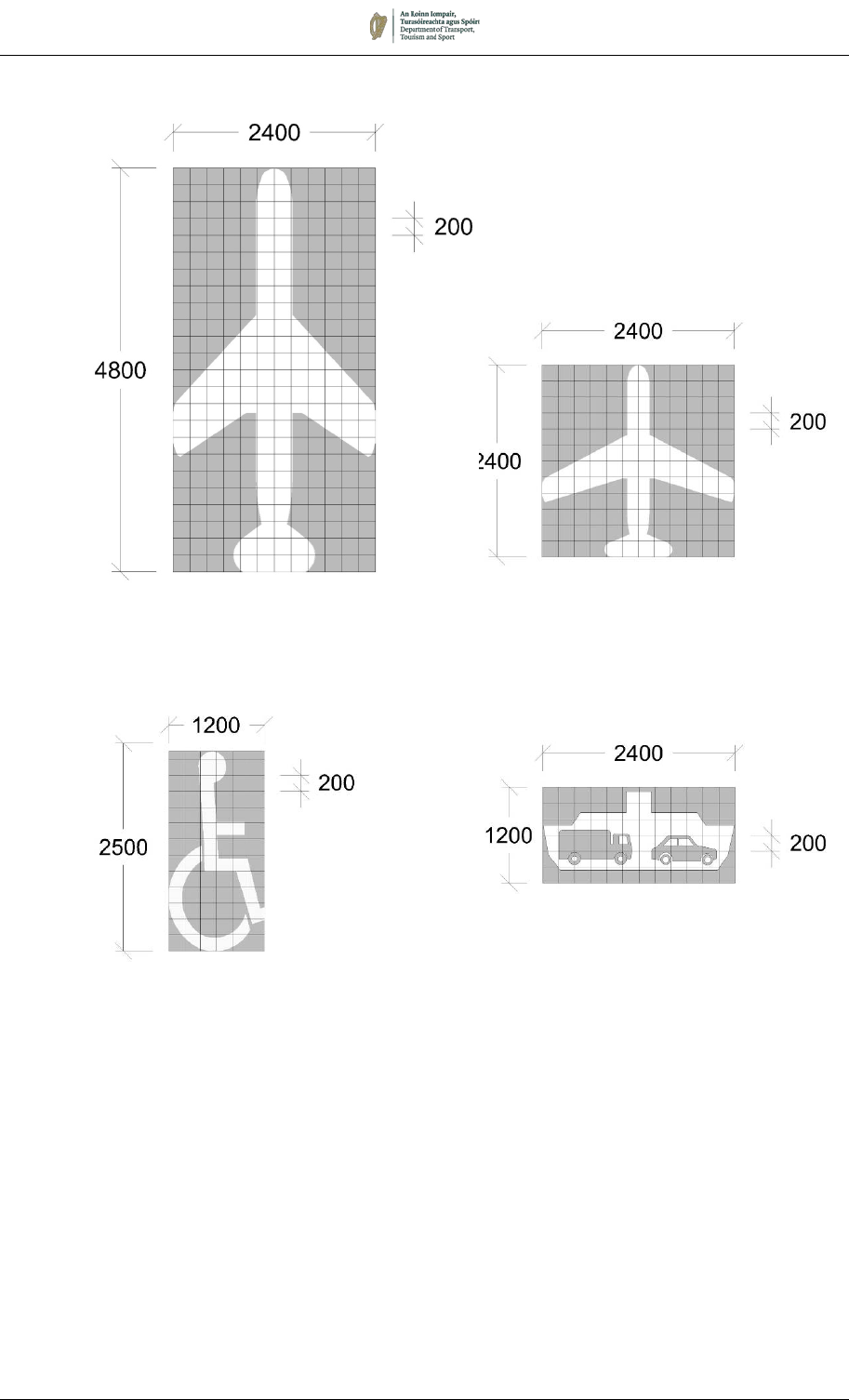
August 2019 7/112
Appendix 7B: Airport, Ferry and Disabled Persons Symbols
Figure 7.63:
Construction of M 127 Airport Symbol
Figure 7.64:
Construction of M 128 Ferry Symbol
Figure 7.65:
Construction of RRM 015
Disabled Persons Symbol
August 2019 7/113
Appendix 7C: Schedule of Road Markings
Sign Number
Description See Section
Regulatory Road Markings
RRM 001
Continuous Single Centre Line
7.3
(7.2, 7.4, 7.10 – 7.12, 7.15, 7.16)
RRM 002A & B
Broken Centre Line 7.3 (7.10, 7.11, 7.13, 7.15)
RRM 002C & D
Centre Warning Line 7.3 (7.4, 7.10, 7.11, 7.15)
RRM 003A & B
Lane Line 7.3 (7.4, 7.10 – 7.14, 7.16)
RRM 003C
Modified Lane Line 7.13 (7.3)
RRM 004
Direction Arrow – Straight Ahead 7.5 (7.7, 7.11, 7.12)
RRM 005
Direction Arrow – Left 7.5 (7.11)
RRM 006
Direction Arrow – Right 7.5 (7.11)
RRM 007
Single Yellow Line 7.6
RRM 008
Double Yellow Line 7.6
RRM
009 Loading Bay 7.6 (App 7A)
RRM 010
School Keep Clear 7.5
RRM 011
Parking Bays – Parallel 7.6
RRM 012
Parking Bays – Parallel with Buffer Zone 7.6
RRM 013
Parking Bays – Perpendicular 7.6
RRM 014
Parking Bays – Angled 7.6
RRM 015
Disabled Persons Symbol 7.6 (App 7B)
RRM 016
Parking Bays – Unsegregated 7.6
RRM 017
Stop Line
7.2
(7.3, 7.5, 7.11, 7.12, 7.15, 7.16)
RRM 018
Yield Line 7.2 (7.3, 7.5, 7.11)
RRM 018C
Cycle Track Yield Line 7.8 (7.2)
RRM 019
No Entry Line 7.2 (7.5, 7.11, 7.13)
RRM 020
Yellow Box Marking 7.9 (7.7, 7.15)
RRM 021
Hatch Marking 7.4 (7.3, 7.10, 7.13, 7.14)
RRM 022
Cycle Track Edge Line 7.8
RRM 023
Cycle Track Broken Edge Line 7.8
RRM 024
Bus Lane Line and LÁNA BUS Marking 7.7
RRM 025
Edge of Carriageway Line (Broken)
7.3
(7.4, 7.8, 7.10, 7.11, 7.13 – 7.15)
RRM 026
Edge of Carriageway Line (Continuous) 7.3 (7.4, 7.10)

August 2019 7/114
Sign Number
Description See Section
RRM 027
Edge of Carriageway Line (Continuous White)
7.3 (7.4, 7.10, 7.11, 7.13, 7.14)
RRM 028
Merge/Diverge Lane Line 7.3 (7.10, 7.14)
RRM 029
Taxi Rank Marking 7.6
RRM 030
Bus Stop Marking 7.7
RRM 031
Tram Stop Line 7.2
RRM 032
Tram Lane Line 7.7
RRM 033
Mini-Roundabout Marking 7.13
RRM 034
Electric Vehicle Recharging Bay Markings 7.6
Sign Number
Description See Section
Non
-regulatory Road Markings
M 100
Deflection Arrow (Left) 7.5 (7.3, 7.4)
M 101
Deflection Arrow (Right) 7.5 (7.7, 7.8)
M 102
Bifurcation Arrow 7.5
M 103
Two-Lane Arrow 7.5
M 104
Diagonal Hatch Marking within Double Line
System
7.3
M 105
Lane Destination Marking 7.5
M 106
SLOW Worded Marking 7.5
M 107L & R
LOOK LEFT / LOOK RIGHT Marking 7.5 (7.7)
M 108
Speed Marking 7.5
M 109
LÁNA TRAM Worded Marking 7.7
M 110
Swept Path Marking 7.7
M 111
Pedestrian Symbol 7.8
M
112 Traffic Calming Triangle 7.17
M 113
Yellow Bar Markings 7.18
M 114
STOP Worded Marking 7.5 (7.2, 7.11, App 7A)
M 115
Triangular Yield Marking 7.5 (7.2, 7.11, 7.13)
M 115C
Cycle Track Triangular Yield Marking 7.8
M 116
Cycle Symbol 7.8
M 117
Cycle Track Direction Arrow – Left 7.8
M 118
Cycle Track Direction Arrow – Straight Ahead 7.8
M 119
Cycle Track Direction Arrow – Right 7.8
August 2019 7/115
Sign Number
Description See Section
M 120
Chainage and Emergency Telephone Marking
7.5
M 121
School Crossing Patrol Point 7.5
M 122
Exit Boundary Line at Level Crossing 7.15
M 123
Back of Footway Line at Level Crossing 7.15
M 124
Direction Arrow – Ahead & Left 7.5 (7.12)
M 125
Direction Arrow – Ahead & Right 7.5 (7.12)
M 126
Direction Arrow – Left & Right 7.5
M 127
Airport Destination Marking 7.5 (App 7B)
M 128
Ferry Port Destination Marking 7.5 (App 7B)
M 129
Broken Bus Lane Line 7.7
M 130
Bus Lane Ends Arrow 7.7
M 130L & R
Bus Lane Ends Arrow – L and R Variants 7.7
M
131 Pedestrian Line 7.16 (7.12)
Sign Number
Name See Section
Pedestrian Crossings (Regulatory)
RPC 001
Zebra Pedestrian Crossing 7.16 (7.2)
RPC 002
Zigzag Markings 7.16
