
MUTCD 11th Edition Page 203
Month 2023December 2023
Sect. 2D.01
CHAPTER 2D. GUIDE SIGNS—CONVENTIONAL ROADS
Chapter 2D Subchapter and Section Organization
GENERAL DESIGN
2D.01 Scope of Conventional Road Guide Sign Standards and Application
2D.02 Color,Retroreection,andIllumination
2D.03 Size of Signs
2D.04 Lettering Style
2D.05 Size of Lettering
2D.06 AmountofLegend
2D.07 Abbreviations
2D.08 Arrows
ROUTE SIGNS AND AUXILIARY PLAQUES
2D.09 NumberedHighwaySystems
2D.10 Route Signs and Auxiliary Plaques
2D.11 Design of Route Signs
2D.12 Design of Route Sign Auxiliary Plaques
2D.13 Junction Auxiliary Plaque (M2-1P)
2D.14 CombinationJunctionSign(M2-2)
2D.15 Cardinal Direction Auxiliary Plaques (M3-1P through M3-4P)
2D.16 Alternative Route Auxiliary Plaques (M4-1P through M4-4P)
2D.17 ALTERNATE Auxiliary Plaques (M4-1P and M4-1aP)
2D.18 BY-PASS Auxiliary Plaque (M4-2P)
2D.19 BUSINESSAuxiliaryPlaque(M4-3P)
2D.20 TRUCK Auxiliary Plaque (M4-4P)
2D.21 TO Auxiliary Plaque (M4-5P)
2D.22 END Auxiliary Plaque (M4-6P)
2D.23 BEGINAuxiliaryPlaque(M4-14P)
2D.24 TEMPORARY Auxiliary Plaques (M4-7P and M4-7aP)
2D.25 TemporaryDetourSignsandAuxiliaryPlaques
2D.26 Advance Turn Arrow Auxiliary Plaques (M5-1P, M5-2P, and M5-3P)
2D.27 Lane Designation Auxiliary Plaques (M5-4P, M5-5P, and M5-6P)
2D.28 Directional Arrow Auxiliary Plaques (M6 Series)
SIGN ASSEMBLIES
2D.29 RouteSignAssemblies
2D.30 JunctionAssembly
2D.31 AdvanceRouteTurnAssembly
2D.32 DirectionalAssembly
2D.33 ConrmingorReassuranceAssemblies
2D.34 TrailblazerAssembly
DESTINATION AND DISTANCE SIGNS
2D.35 Destination and Distance Signs
2D.36 Destination Signs (D1 Series)
2D.37 Overhead Arrow-per-Lane Destination Guide Signs
2D.38 CombinationLane-Use/DestinationOverheadGuideSign(D15-1)
2D.39 DestinationSignsatCircularIntersections
2D.40 Destination Signs at Jughandles

Page 204 MUTCD 11th Edition
Month 2023December 2023
Sect. 2D.01
2D.41 DestinationSignsatIntersectionswithIndirectTurningMovements
2D.42 Location of Destination Signs
2D.43 Distance Signs (D2 Series)
2D.44 Location of Distance Signs
STREET NAME AND PARKING SIGNS
2D.45 StreetNameSigns(D3-1andD3-1a)
2D.46 AdvanceStreetNameSigns(D3-2Series)
2D.47 Parking Area Guide Sign (D4-1)
2D.48 PARK-RIDESign(D4-2)
FREEWAY INTERCHANGE APPROACH SIGNS
2D.49 SigningonConventionalRoadsonApproachestoInterchanges
2D.50 Freeway Entrance Signs (D13-3 and D13-3a)
WEIGH STATION, CROSSOVER, TRUCK AND PASSING LANE, AND EMERGENCY AND SLOW
VEHICLE TURN-OUT SIGNS
2D.51 WEIGHSTATIONSigning(D8Series)
2D.52 Crossover Signs (D13-1 and D13-2)
2D.53 Truck and Passing Lane Signs (D17-1 through D17-4)
2D.54 EmergencyandSlowVehicleTurn-OutSigns(D17-5throughD17-7)
OTHER GUIDE SIGNS
2D.55 CommunityWayndingSigns
2D.56 SigningofNamedHighwaysforMappingandAddressPurposes
2D.57 National Scenic Byways Sign and Plaque (M10-1 and M10-1aP)
2D.58 State-DesignatedScenicByway,HistoricTrail,andAutoTourRouteSigns
2D.59 EmergencyRoutingSignsandPlaques(M4-11andM4-12 Series)
SIGNING AT AIRPORTS
2D.60 Signing at Airports

MUTCD 11th Edition Page 205
Month 2023December 2023
GENERAL DESIGN
Section 2D.01 Scope of Conventional Road Guide Sign Standards and Application
Standard:
01 The provisions of this Chapter shall apply to any road or street other than expressways and freeways,
except as otherwise provided in this Manual.
Support:
02 Guidesignsdirectroadusersalongstreetsandhighways;informthemofintersectingroutes;directthemto
cities,towns,villages,orotherimportantdestinations;identifynearbyriversandstreams,parks,forests,andhistorical
sites;andprovideinformationthatwillhelpthemalongtheirwayinthemostsimpleanddirectmannerpossible.
Guidance:
03 The selection of primary or control destinations (those displayed consistently over longer distances
along a route) displayed on guide signs should be meaningful to road users in navigation and orientation.
The destinations selected should be identiable on ofcial maps.
04 The familiarity of the road users with the road should be considered in determining the need for guide signs
on low-volume roads.
Support:
05 Low-volumeroadsgenerallydonotrequireguidesignstotheextentthattheyareneededonhigherclasses
ofroads.Becauseguidesignsaretypicallyonlybenecialasanavigationalaidforroaduserswhoareunfamiliar
withalow-volumeroad,guidesignsmightnotbeneededonlow-volumeroadsthatserveonlylocaltrafc.
06 Guidesigns,otherthanStreetNamesigns,generallyarenotusedonlow-volumeruralroadsexceptasneeded
toguideroadusersbacktothemajorroadways.
Guidance:
07 If used on low-volume roads, destination names should be as specic and descriptive as possible. Destinations
such as campgrounds, ranger stations, recreational areas, and the like should be clearly indicated so that they
are not interpreted to be communities or locations with road user services.
Option:
08 Guidesignsmaybeusedonlow-volumeroadsatintersectionstoprovideinformationforroadusersreturning
to a higher class of roads.
Support:
09 Chapter2Aaddressesplacement,location,andothergeneralcriteriaforsigns.
Section 2D.02 Color, Retroreection, and Illumination
Support:
01 Requirementsforillumination,retroreection,andcolorarestatedunderthespecicheadingsforindividual
guide signs or groups of signs. General provisions are given in 2A.06, 2A.21, and 2A.22.
Standard:
02 Except as otherwise provided in this Manual for individual signs or groups of signs, guide signs on
streets and highways shall have a white message and border on a green background. All messages, borders,
and legends shall be retroreective and all backgrounds shall be retroreective or illuminated.
Support:
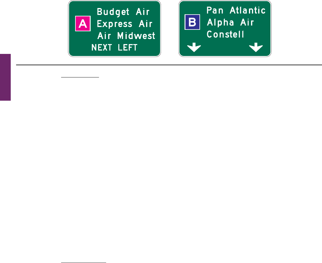
03 Colorcodingissometimesusedtohelproadusersdistinguishbetweenmultiplepotentiallyconfusing
destinations.Examplesofvaluableusesofcolorcodingincludeguidesignsforroadwaysapproachingorinside
anairportpropertywithmultipleterminalsservingmultipleairlines,andcommunitywayndingguidesignsfor
varioustrafcgeneratordestinationswithinacommunityorarea.
Standard:
04 Except as otherwise provided in this Manual, different color sign backgrounds shall not be used to
provide color coding of destinations. The color coding shall be accomplished by the use of different colored
square or rectangular sign panels on the face of the guide signs (see Figure 2D-1).
Option:
05 Thedifferentcoloredsignpanelsonthefaceofasignmayincludeablackorwhite(whicheverprovidesthe
bettercontrastwiththepanelcolor)letter,numeral,orotherappropriatedesignationtoidentifyanairportterminal
or other destination.
Support:
06 Section2D.55containsspecicprovisionsregardingCommunityWayndingguidesigns.
Sect. 2D.01 to 2D.02
Page 206 MUTCD 11th Edition
Month 2023December 2023
Sect. 2D.03 to 2D.04
Section 2D.03 Size of Signs
Standard:
01 Except as provided in Section 2A.07, the minimum sizes of conventional road guide signs that have
standardized designs shall be as shown in Table 2D-1.
Support:
02 Section2A.07containsinformationregardingtheapplicabilityofthevariouscolumnsinTable2D-1.
Option:
03 SignslargerthanthoseshowninTable2D-1maybeused(seeSection2A.07).
Support:
04 For other guide signs, the legends are so variable that a standardized design or size is not appropriate.
Thesignsizeisdeterminedprimarilybythelengthofthemessage,andthesizeofletteringandspacingnecessary
for proper legibility.
Option:
05 Reducedletterheight,reducedinterlinespacing,andreducededgespacingmaybeusedonguidesignsifsign
sizemustbelimitedbyfactorssuchaslanewidthorverticalorlateralclearance.
Guidance:
06 Reduced spacing between the letters or words on a line of legend should not be used as a means of reducing
the overall size of a guide sign, except where determined necessary by engineering judgment to meet unusual
lateral-space constraints. In such cases, the legibility distance of the sign legend should be the primary
consideration in determining whether to reduce the spacing between the letters or the words or between the words
and the sign border, or to reduce the letter height.
07 When a reduction in the prescribed size is necessary, the design used should be as similar as possible to the
design for the standard size.
Section 2D.04 Lettering Style
Standard:
01 The design of upper-case letters, lower-case letters, numerals, route shields, and spacing shall be as
provided in the “Standard Highway Signs” publication (see Section 1A.05).
02 The lettering for names of places, streets, and highways on conventional road guide signs shall be a
combination of lower-case letters with initial upper-case letters (see Section 2A.08). The nominal loop height
of the lower-case letters shall be ¾ the height of the initial upper-case letter. When a mixed-case legend
letter height is specied referring only to the initial upper-case letter, the height of the lower-case letters
that follow shall be determined by this proportion. When the height of a lower-case letter is referenced,
the reference is made to the nominal loop height. The height of the initial upper-case letter shall also be
determined by this proportion.
03 All other word legends on conventional road guide signs shall be in upper-case letters.
04 The unique letter forms for each of the Standard Alphabet series shall not be stretched, compressed,
warped, or otherwise manipulated. Modications to the length of a word for a given letter height and series
shall be accomplished only by the methods described in Section 2D.03.
Figure 2D-1. Examples of Color-Coded Destination Guide Signs

MUTCD 11th Edition Page 207
Month 2023December 2023
Sect. 2D.04
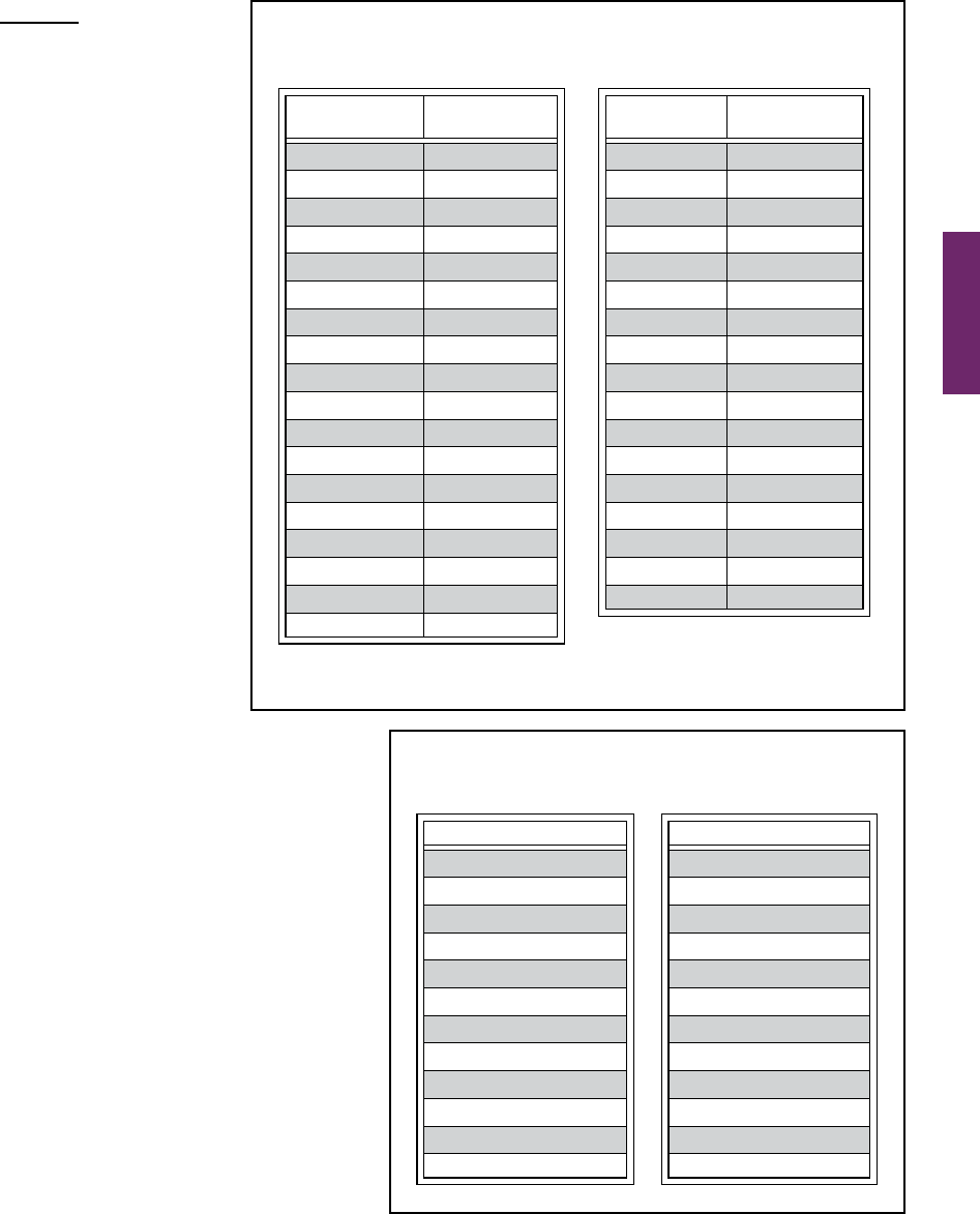
Table 2D-1. Conventional Road Guide Sign and Plaque Sizes (Sheet 1 of 2)
Sign or Plaque Designation Section
Conventional
Road
Minimum Oversized
Interstate Route (1 or 2 digits) M1-1,1a 2D.11 24 x 24 — 36 x 36
Interstate Route (3 digits) M1-1,1a 2D.11 30 x 24 — 45 x 36
Off-Interstate Route (1 or 2 digits) M1-2,3 2D.11 24 x 24 — 36 x 36
Off-Interstate Route (3 digits) M1-2,3 2D.11 30 x 24 — 45 x 36
U.S. Route (1 or 2 digits) M1-4 2D.11 24 x 24 — 36 x 36
U.S. Route (3 digits) M1-4 2D.11 30 x 24 — 45 x 36
State Route (1 or 2 digits) M1-5 2D.11 24 x 24 — 36 x 36
State Route (3 digits) M1-5 2D.11 30 x 24 — 45 x 36
County Route M1-6 2D.11 24 x 24 — 36 x 36
Forest Route M1-7 2 D.11 24 x 24 18 x 18 36 x 36
Junction (plaque) M2-1P 2D.13 21 x 15 — 30 x 21
Combination Junction (2 route signs) M2-2 2D.14 60 x 48* — —
Cardinal Direction (plaque) M3-1P,2P, 3 P,4P 2D.15 24 x 12 — 36 x 18
Alternate (plaque) M4-1P,1aP 2D.17 24 x 12 — 36 x 18
By-Pass (plaque) M4-2P 2D.18 24 x 12 — 36 x 18
Business (plaque) M4-3P 2D.19 24 x 12 — 36 x 18
Truck (plaque) M4-4P 2D.20 24 x 12 — 36 x 18
To (plaque) M4-5P 2D.21 24 x 12 — 36 x 18
End (plaque) M4-6P 2D.22 24 x 12 — 36 x 18
Temporary (plaque) M4-7P,7a P 2D.24 24 x 12 — 36 x 18
Emergency Route M4 -11 2D.59 30 x 30 — —
Emergency Route M4 -11a 2D.59 30 x 30 — —
Emergency Route To (plaque) M4 -11bP, 11cP 2D.59 30 x 18 — —
End Emergency Route M4-12 2D.59 24 x 18 — —
Begin (plaque) M4-14P 2D.23 24 x 12 — 36 x 18
Advance Turn Arrow (plaque) M5 -1P,2P, 3 P 2D.26 21 x 15 — 30 x 21
Lane Designation (plaque) M5 - 4P,5P, 6P 2D.27 24 x 18 — 36 x 24
Directional Arrow (plaque)
M6 -1P,2P, 2 a P,
3P,4 P, 5P,6 P,7 P
2D.28 21 x 15 — 30 x 21
National Scenic Byway M10-1 2D.57 24 x 24 — —
National Scenic Byway (plaque) M10-1aP 2D.57 24 x 12 — —
Byway Identification M10-2 2D.58 24 x 24 — —
Byway Identification (plaque) M10-2aP 2D.58 24 x 12 — —
State Scenic Byway System M10-3 2D.58 24 x 24 — —
State Scenic Byway - Simple Graphic and Byway
Identification
M10-3a 2D.58 24 x 24 — —
Scenic Byway (plaque) M10-3bP 2D.58 24 x 12 — —
National Historic Trail - Identification M11-1 2D.58 24 x 24 — —
National Historic Trail - Historic Route (plaque) M11-1aP 2D.58 24 x 12 — —
National Historic Trail - Crossing (plaque) M11-1bP 2D.58 24 x 12 — —
National Historic Trail - Auto Tour Route (plaque) M11-1cP 2D.58 24 x 12 — —
National Historic Trail - Distance (plaque) M11-1dP 2D.58 24 x 12 — —
Destination (1 line) D1-1 2D.36 Varies x 18 — —
Destination and Distance (1 line) D1-1a 2D.36 Varies x 18 — —
Circular Intersection Destination (1 line) D1-1d 2D.39 Varies x 18 — —
Circular Intersection Departure Guide D1-1e 2D.39 Varies x 42*
— —
Destination (2 lines) D1-2 2D.36 Varies x 30 — —
Destination and Distance (2 lines) D1-2a 2D.36 Varies x 30 — —
Circular Intersection Destination (2 lines) D1-2d 2D.39 Varies x 30 — —

Page 208 MUTCD 11th Edition
Month 2023December 2023
Sect. 2D.05
Section 2D.05 Size of Lettering
Support:
01 Signlegibilityisadirectfunctionoflettersizeandspacing.Legibilitydistancehastobesufcienttogiveroad
usersenoughtimetoreadandcomprehendthesign.Underoptimumconditions,aguidesignmessagecanberead
and understood in a brief glance. The legibility distance takes into account factors such as inattention, blocking
of view by other vehicles, unfavorable weather, inferior eyesight, or other causes for delayed or slow reading.
Whereconditionspermit,repetitionofguideinformationonsuccessivesignsgivestheroadusermorethanone
opportunitytoobtaintheinformationneeded.
Standard:
02 Design layouts for conventional road guide signs showing interline spacing, edge spacing, and other
specication details shall be as shown in the “Standard Highway Signs” publication (see Section 1A.05).
Sign or Plaque Designation Section
Conventional
Road
Minimum Oversized
Destination (3 lines) D1-3 2D.36 Varies x 42 — —
Destination and Distance (3 lines) D1-3a 2D.36 Varies x 42 — —
Circular Intersection Destination (3 lines) D1-3d 2D.39 Varies x 42 — —
Circular Intersection Diagrammatic Destination D1-5 2D.39 Varies x 72* — —
Circular Intersection Diagrammatic Destination,
Right-Turn Bypass
D1-5a 2D.39 Varies x 78* — —
Distance (1 line) D2-1 2D.43 Varies x 18 — —
Distance (2 lines) D2-2 2D.43 Varies x 30 — —
Distance (3 lines) D2-3 2D.43 Varies x 42 — —
Street Name (1 line) D3-1,1a 2D.45 Varies x 12 Varies x 8 Varies x 18
Overhead Street Name (1 line) D3-1,1a 2D.45 Varies x 24 — —
Street Name (2 lines) D3-1,1a 2D.45 Varies x 24 Varies x 15 Varies x 33
Overhead Street Name (2 lines) D3-1,1a 2D.45 Varies x 48 — —
Advance Street Name (2 lines) D3-2 2D.46 Varies x 30 — —
Advance Street Name (3 lines) D3-2 2D.46 Varies x 42 — —
Advance Street Name (4 lines) D3-2 2D.46 Varies x 54 — —
Parking Area Directional D4-1 2D.47 30 x 24 18 x 15 —
Park - Ride D4-2 2D.48 30 x 36 24 x 30 36 x 48
Advance Weigh Station Distance D8-1 2D.51 78 x 60 60 x 48 96 x 72
Weigh Station Ahead D8-1a 2D.51 66 x 48 48 x 36 —
Weigh Station Advance Direction D8-2 2D.51 84 x 72 66 x 54 108 x 90
Weigh Station Entrance Direction D8-3 2D.51 66 x 60 48 x 42 84 x 78
Crossover D13-1,2 2D.52 60 x 30 —
78 x 42
Freeway Entrance D13-3 2D.50 48 x 30 — —
Freeway Entrance (Directional) D13-3a 2D.50 48 x 42 — —
Combination Lane Use / Destination D15-1 2D.38 Varies x 96 — —
Next Truck Lane D17-1 2D.53 42 x 48 — 60 x 66
Advance Truck Lane D17-2 2D.53 42 x 42 — 60 x 54
Next Passing Lane D17-3 2D.53 42 x 48 — 60 x 66
Advance Passing Lane D17- 4 2D.53 42 x 42 — 60 x 54
Advance Emergency Turn-Out D17-5 2D.54 60 x 36 — 78 x 54
Emergency Turn-Out (Directional) D17- 6 2D.54 60 x 36 — 78 x 60
Advance Slow Vehicle Turn-Out D17-7 2D.54 72 x 36 — 96 x 54
*The size shown is for a typical sign. The size should be determined based on the amount of legend required for the sign.
Notes: 1. Larger signs may be used when appropriate
2. Dimensions in inches are shown as width x height
Table 2D-1. Conventional Road Guide Sign and Plaque Sizes (Sheet 2 of 2)

MUTCD 11th Edition Page 209
Month 2023December 2023
Sect. 2D.05 to 2D.07
03 Except as otherwise provided in this Manual, the principal legend on post-mounted guide signs shall be
in letters and numerals at least 6 inches in height for all upper-case letters, or a combination of 6 inches in
height for upper-case letters and 4.5 inches in nominal loop height (see Section 2D.04) for lower-case letters.
On low-volume roads with speeds of 25 mph or less, and on urban streets with speeds of 25 mph or less, the
principal legend on post-mounted guide signs shall be in letters at least 4 inches in height for all upper-case
letters, or a combination of 4 inches in height for upper-case letters and 3 inches in nominal loop height for
lower-case letters.
04 Except as otherwise provided in this Manual, the principal legend on overhead guide signs shall be
in letters and numerals at least 6 inches in height for all upper-case letters, or a combination of 6 inches
in height for upper-case letters and 4.5 inches in nominal loop height (see Section 2D.04) for lower-
case letters.
Guidance:
05 Lettering sizes should be consistent on any particular class of highway.
06 The minimum lettering and numeral sizes provided in this Manual (see Table 2D-2) should be exceeded where
conditions indicate a need for greater legibility.
Section 2D.06 Amount of Legend
Support:
01 Thelongerthelegendonaguidesign,thelongeritwilltakeroaduserstorecognizeandcomprehendit,
regardless of letter size.
Guidance:
02 Except where otherwise provided in this Manual, guide signs should be limited to no more than three lines
of destinations, which include place names, route numbers, street names, and cardinal directions. Where two or
more signs are included in the same overhead display, the amount of legend should be further minimized. Where
appropriate, a distance message or action information, such as an exit number, NEXT RIGHT, or directional
arrows, should be provided on guide signs in addition to the destinations.
Section 2D.07 Abbreviations
Support:
01 Theuseofcommonlyrecognizedabbreviationsforcertainwordscanbeusefulinreducingthereadingtime
andimprovequickercomprehensionofasignmessage.Descriptorsanddirectionalorquadrantorientationsfor
streetnamesanddestinations,suchasBoulevard(Blvd),North(N),andSouthwest(SW),aresomeexamples
ofcommonlyrecognizedabbreviations.Examplesoftheuseofsomeguidesignabbreviationsareshownin
Figure 2D-2.
Standard:
02 The words NORTH, SOUTH, EAST, and WEST shall not be abbreviated when used to indicate
cardinal directions of numbered or named highways on guide signs.
Guidance:
03 Abbreviations should be kept to a minimum; however, they are useful when complete destination messages
produce excessively long signs. If used, abbreviations should be unmistakably recognized by road users
(see Section 1D.08). Longer commonly used words that are not part of a proper name and are readily
recognizable,
such as street name descriptors (such as Street, Boulevard, or Avenue), should be abbreviated as
provided in Table 2D-3 to expedite recognition of the sign legend by reducing the amount and complexity of the
legend. Shorter street name descriptors, such as those shown in Table 2D-4, should not be abbreviated.
04 Periods, apostrophes, question marks, ampersands, or other punctuation or characters that are not letters,
numerals, or hyphens should not be used in abbreviations, unless necessary to avoid confusion.
05 The solidus is intended to be used for fractions only and should not be used to separate words on the same
line of legend. Instead, a hyphen should be used for this purpose, such as “TRUCKS – BUSES.”

December 2023
Page 210 MUTCD 11th Edition
Sect. 2D.07
Table 2D-2. Recommended Minimum Letter and Numeral Sizes for
Conventional Road Guide Signs According to Speed* (Sheet 1 of 2)
A - Post-Mounted Signs
Type of Sign
Single-Lane Multi-Lane
Less than
30 mph
30-40 mph
Greater than
40 mph
Less than
30 mph
30-40 mph
Greater than
40 mph
A. Intersection or Interchange Advance Guide Signs and Entrance Direction Guide Signs
Interstate or Off-Interstate Business Route Signs
Numerals** 6 9 14 9 9 14
1- or 2-Digit Shields 18 x 18 24 x 24 36 x 36 24 x 24 24 x 24 36 x 36
3-Digit Shields 22.5 x 18 30 x 24 45 x 36 30 x 24 30 x 24 45 x 36
U.S. or State Route Signs
Numerals 9 12 18 12 12 18
1- or 2-Digit Shields 18 x 18 24 x 24 36 x 36 24 x 24 24 x 24 36 x 36
3-Digit Shields 22.5 x 18 30 x 24 45 x 36 30 x 24 30 x 24 45 x 36
County Route Signs
Numerals 6 8 10 8 8 10
1-, 2-, or 3-Digit Shields 18 x 18 24 x 24 36 x 36 24 x 24 24 x 24 36 x 36
U.S. or State Route Text Identification (Examples: U S 56, Md 2)
Numerals & Letters 8 12 15 10 12 15
Cardinal Directions (NORTH, SOUTH, EAST, WEST)
First Letter - Upper-Case 6 8 10 8 8 10
Rest of Word - Upper-Case 5 6 8 6 6 8
Auxiliary and Alternative Route Legends (Examples: JCT, TO, ALT, BUSINESS)
Words - Upper-Case 5 6 8 6 6 8
Names of Destinations or Roads (Examples: Springfield, Main St, 2nd Ave)
Leading Upper-Case Letter
or Numerals
6 8 10.67 8 10.67 13.33
Following Lower-Case Letters
or Ordinals**
4.5 6 8 6 8 10
Distance or Action Messages (Examples: 2 MILES, 1/2 MILE, KEEP RIGHT)
Distance Numerals 6 6 8 6 8 10
Distance Fraction Numerals 4.5 4.5 6 4.5 6 8
Distance Words - Upper-Case 4.5 4.5 6 4.5 6 8
Action Message Words -
Upper-Case
6 6 8 6 8 10
B. Destination and Other Guide Signs
Names of Destinations or Roads (Examples: Springfield, Main St, 2nd Ave)
Leading Upper-Case Letter
or Numerals
4 6 8 6 8 10.67
Following Lower-Case Letters
or Ordinals***
3 4.5 6 4.5 6 8
Distance or Action Messages (Examples: 2 MILES, 1/2 MILE, KEEP RIGHT)
Distance Numerals 5 6 8 5 6 8
Distance Fraction Numerals 4 4.5 6 4 4.5 6
Distance Words - Upper-Case 4 4.5 6 4 4.5 6
Action Message Words -
Upper-Case
5 6 8 6 6 8

December 2023
MUTCD 11th Edition Page 211
Sect. 2D.07
Table 2D-2. Recommended Minimum Letter and Numeral Sizes for
Conventional Road Guide Signs According to Speed* (Sheet 2 of 2)
B - Overhead-Mounted Signs
Type of Sign Less than 35 mph 35-55 mph Greater than55 mph
A. Intersection or Interchange Advance Guide Signs and Entrance Direction Guide Signs
Interstate, U.S., State, or Off-Interstate Business Route Signs
Numerals** 6 9 14
1- or 2-Digit Shields 18 x 18 24 x 24 36 x 36
3-Digit Shields 22.5 x 18 30 x 24 45 x 36
U.S. or State Route Signs
Numerals 9 12 18
1- or 2-Digit Shields 18 x 18 24 x 24 36 x 36
3-Digit Shields 22.5 x 18 30 x 24 45 x 36
County Route Signs
Numerals 6 8 10
1-, 2-, or 3-Digit Shields 18 x 18 24 x 24 36 x 36
U.S. or State Route Text Identification (Examples: U S 56, Md 2)
Numerals & Letters 8 12 15
Cardinal Directions (NORTH, SOUTH, EAST, WEST)
First Letter - Upper-Case 6 8 12
Rest of Word - Upper-Case 5 6 10
Auxiliary and Alternative Route Legends (Examples: JCT, TO, ALT, BUSINESS)
Words - Upper-Case 5 6 10
Names of Destinations or Roads (Examples: Springfield, Main St, 2nd Ave)
Leading Upper-Case Letter
or Numerals
6
8 (min.)
10.67 (des.)
13.33 (min.)
16 (des.)
Following Lower-Case Letters
or Ordinals**
4.5
6 (min.)
8 (des.)
10 (min.)
12 (des.)
Distance or Action Messages (Examples: 2 MILES, 1/2 MILE, KEEP RIGHT)
Distance Numerals 6
6 (min.)
8 (des.)
12 (min.)
15 (des.)
Distance Fraction Numerals 4.5
4.5 (min.)
6 (des.)
10 (min.)
12 (des.)
Distance Words - Upper-Case 4.5
4.5 (min.)
6 (des.)
10 (min.)
12 (des.)
Action Message Words -
Upper-Case
6
6 (min.)
8 (des.)
12 (min.)
15 (des.)
B. Destination and Other Guide Signs
Names of Destinations or Roads (Examples: Springfield, Main St, 2nd Ave)
Leading Upper-Case Letter
or Numerals
6
8 (min.)
10.67 (des.)
13.33 (min.)
16 (des.)
Following Lower-Case Letters
or Ordinals**
4.5
6 (min.)
8 (des.)
10 (min.)
12 (des.)
Distance or Action Messages (Examples: 2 MILES, 1/2 MILE, KEEP RIGHT)
Distance Numerals 6
6 (min.)
8 (des.)
12 (min.)
15 (des.)
Distance Fraction Numerals 4.5
4.5 (min.)
6 (des.)
10 (min.)
12 (des.)
Distance Words - Upper-Case 4.5
4.5 (min.)
6 (des.)
10 (min.)
12 (des.)
Action Message Words -
Upper-Case
6
6 (min.)
8 (des.)
12 (min.)
15 (des.)
* Except as provided otherwise in this Manual
** Minimum size listed for 3-digit shields. Larger numeral sizes used for 1-digit, some 2-digit, and some 3-digit shields. See the Standard
Highways Signs publication for more information on Route Sign numeral heights and Standard Alphabet series.
*** Lower-case letter height (loop height) is determined by the initial upper-case letter height (see Sec. 2A.08)
Notes: 1. Sizes are shown in inches and where applicable are shown as width x height
2. For Street Name (D3-1 Series) signs, see Table 2D-6
3. The 18-inch route shield size is not for independent use, such as in Directional or Confirmation Assemblies.
Page 212 MUTCD 11th Edition
Month 2023December 2023
Sect. 2D.07
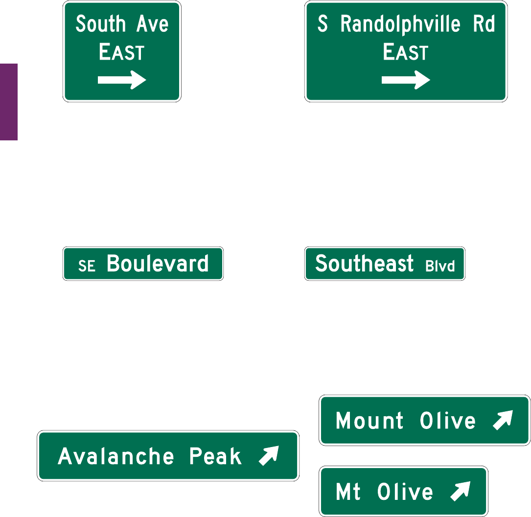
Figure 2D-2. Examples of Uses of Abbreviations on Guide Signs
“South” is the street name and shall not
be abbreviated.
“EAST” is the cardinal direction of travel
and shall not be abbreviated.
”Avenue” is the street name descriptor
with a recognizable abbreviation* and
should be abbreviated.
“South” is a cardinal direction and may
be abbreviated.
“EAST” is the cardinal direction of travel
and shall not be abbreviated.
“Road” is the street name descriptor with
a recognizable abbreviation* and should
be abbreviated.
A – Cardinal directions and orientations
“Southeast” is a quadrant cardinal
orientation and should be abbreviated.
”Boulevard” is the street name and shall
not be abbreviated.
“Southeast” is the street name and shall
not be abbreviated.
“Boulevard” is the street name descriptor
with a recognizable abbreviation* and
should be abbreviated.
B – Quadrant and cardinal directions
“Peak” is a geographical feature as a descriptor within
a proper name. When a geographical feature descriptor
does not have a recognizable abbreviation, it shall not
be abbreviated.
*
See Tables 1D-1 and 2D-3 for the abbreviations that are acceptable for use on signs
“Mount” is a geographical feature as a
descriptor within a proper name. When a
geographical feature descriptor has a
recognizable abbreviation, it may
be abbreviated.
C – Other descriptors within proper names
OR
MUTCD 11th Edition Page 213
Month 2023December 2023
Sect. 2D.08
Section 2D.08 Arrows
Support:
01 Arrows are used for lane
assignmentandtoindicatethe
direction toward designated routes or
destinations. Figure 2D-3 shows the
various standard arrow designs that
have been approved for use on guide
signs. Detailed drawings are shown for
thesearrowsinthe“StandardHighway
Signs” publication (see Section 1A.05).
Standard:
02 Except for Overhead Arrow-per-
Lane signs (see Section 2D.37), on
overhead signs where it is desirable
to indicate a lane to be followed, a
down arrow shall be positioned over
the approximate center of the lane
and shall point vertically downward
toward the approximate center of
that lane. Down arrows shall be used
only on overhead guide signs that
restrict the use of specic lanes to
trafc bound for the destination(s)
and/or route(s) indicated by these
arrows. Down arrows shall not be
used unless an arrow can be located
over and pointed to the approximate
center of each lane that can be used
to reach the destination displayed
on the sign.
03 If down arrows are used, having more than one
down arrow pointing to the same lane on a single
overhead sign (or on multiple signs on the same
overhead sign structure) shall not be permitted.
04 Where a roadway is leaving the through lanes,
a directional arrow shall point upward at an angle
that approximates the alignment of the exit roadway
in the vicinity of the point of departure.
05 The Type E directional arrow for circular
intersections shall not be used on any sign that is
not associated with a circular intersection
Guidance:
06 The Type A directional arrow should be used on
guide signs on freeways, expressways, and conventional
roads to indicate the direction to a specic destination
or group of destinations, except as otherwise provided
in this Section and in Section 2E.18.
07 When a directional arrow in a vertical, upward-
pointing orientation is placed to the side of a group of destinations to indicate a through movement, the Type A
directional arrow should be used. When a directional arrow in a vertical, upward-pointing orientation is placed
to the side of a single destination or under a destination or group of destinations, the Type B directional arrow
should be used.
08 The Type B directional arrow should be used on guide signs on conventional roads when placed at any angle
to the side of a single destination or when placed in a horizontal orientation to the side of a group of destinations.
09 The Type C advance turn directional arrow should be used on conventional road guide signs placed in
advance of an intersection where a turn must be made to reach a posted destination or group of destinations.
Table 2D-3. Acceptable Abbreviations
for Street Name Descriptors
Descriptor
Standard
Abbreviation
Avenue Ave
Boulevard Blvd
Bypass Byp
Causeway Cswy
Circle Cir
Corner Cor
Court Ct
Crescent Cres
Drive Dr
East E*
Expressway Expwy
Extension Ext
Freeway Fwy
Highway Hwy
Lane La, Ln
Landing Lndg
North N*
Northeast NE*
Descriptor
Standard
Abbreviation
Northwest NW*
Parkway Pkwy
Place Pl
Plaza Plz
Road Rd
Route Rte
South S*
Southeast SE*
Southwest SW*
Square Sq
Street St
Ter race Ter
Thruway Thwy
Trafficway Trfw y
Trail Tr
Turnpike Tpk
West W*
* For pre-directional or post-directional designations or cardinal orientations,
such as E Main St or 3rd St SW
Table 2D-4. Street Name Descriptors
Not Acceptable for Abbreviation
Descriptor
Alley
Belt
Beltway
Close
Cove
Edge
Gate
Green
Grove
Hill
Loop
Mews
Descriptor
Oval
Pass
Passage
Path
Ridge
Row
Run
Trace
Turn
View
Vista
Walk

Page 214 MUTCD 11th Edition
Month 2023December 2023
Sect. 2D.08
10 The Type D directional arrow should be used primarily for sign applications other than guide signs, except
as provided in Paragraph 15 of this Section.
11 If the Type E directional arrow is used, the principles set forth in Sections 2D.26 through 2D.29 should
be followed.
Option:
12 TheTypeA-Extendeddirectionalarrowmaybeusedonguidesignswhereadditionalemphasisregardingthe
directionisneededrelativetotheamountoflegendonthesign.
13 TheTypeCdirectionalarrowmaybeusedtothesideofthelegendofanoverheadguidesigntoaccentuatea
sharpturnexitmaneuverfromamainlineroadway(seeSection2E.25foradditionalinformationregardingExit
Directionsignsforlowadvisoryrampspeeds).
14 OnconventionalroadsontheapproachtoanintersectionwheretheCombinationLane-Use/Destination
overheadguidesign(seeSection2D.38)isnotused,theTypeCadvanceturndirectionalarrowmaybeused
beneaththelegendofanoverheadguidesigntoindicatethefactthataturnmustbemadefromamandatory
movementlaneoverwhichthesignisplacedtoreachthedestinationordestinationsdisplayedonthesign.
15 TheTypeDdirectionalarrowmaybeusedonpost-mountedguidesignsonconventionalroadswithlower
operatingspeedsiftheheightofthetextonthesignis8inchesorless.TypeDarrowsmaybeusedonaStreet
Name(D3-1only)signdisplayingtwostreetnamestoindicatethedifferentdirectionoftravelforeachstreet.
16 TheTypeEdirectionalarrowmaybeusedonguidesignsonapproachestocircularintersectionstorepresent
theintendeddriverpathstodestinationsinvolvingleft-turnmovementsaroundthecirculatoryisland.
17 The directional and down arrows shown in Figure 2D-3maybeusedonsignsotherthanguidesignsforthe
purposesofprovidingdirectionalguidanceandlaneassignment.
Guidance:
18 Arrows used on guide signs to indicate the directions toward designated routes or destinations should be
pointed at the appropriate angle to clearly convey the direction to be taken. A horizontally-oriented directional
arrow design should be used at right-angle intersections.
19 On a post-mounted guide sign, a directional arrow for a straight-through movement should point upward.
Except as provided in Section 2D.50, for a turn, the arrow on a guide sign should point horizontally or at an
upward angle that approximates the sharpness of the turn.
20 At an exit, an arrow should be placed at the side of the sign that will reinforce the movement of exiting trafc.
The directional arrow design should be used.
Figure 2D-3. Arrows for Use on Guide Signs
Directional arrows
Down arrow
Note: The “Standard Highway Signs”
publication contains the details
of these arrow designs.
Type A Type A - Extended Type B Type C Type D Type E

MUTCD 11th Edition Page 215
Month 2023December 2023
Sect. 2D.08
Standard:
21 If used, the Type C advance turn directional arrow shall display a right or left arrow, the shaft of which
is bent at a 90-degree or oblique angle.
Option:
22 Arrowsmaybeplacedbelowtheprincipalsignlegendorontheappropriatesideofthelegendthatis
consistentwiththedirectionofthemovement.
23 Onapost-mountedsignatanexitwhereplacementofthearrowtothesideofthelegendfarthestfromthe
roadwaywouldcreateanunusuallywidesignthatlimitstheroaduser’sviewofthearrow,thedirectionalarrow
maybeplacedatthebottomportionofthesign,centeredunderthelegend.
Guidance:
24 The width across the arrowhead for the Types A, B, and C directional arrows should be between 1.5 and 1.75
times the height of the upper-case letters of the principal legend on the sign. The width across the arrowhead
for the Type D directional arrow should be at least equal to the height of the upper-case letters of the principal
legend on the sign. For down arrows used on overhead signs, the width across the arrowhead should be
approximately 2 times the height of the upper-case letters of the principal legend on the sign.
Support:
25 Section 2D.37 contains the provisions for arrows used in Overhead Arrow-per-Lane signs on approaches
toconventionalroadintersections.Section2D.41containstheprovisionsforarrowsusedinDiagrammatic
Advance guide signing on approaches to conventional road intersections other than circular intersections. Section
2D.39containstheprovisionsfordiagrammaticarrowsusedinDestinationsignsontheapproachestocircular
intersections (see Figure 2D-11).
26 The“StandardHighwaySigns”publication(seeSection1A.05)containsdesigndetailsandstandardizedsizes
of the various arrows based on ranges of letter heights of principal legends.

Page 216 MUTCD 11th Edition
Month 2023December 2023
Sect. 2D.09 to 2D.11
ROUTE SIGNS AND AUXILIARY PLAQUES
Section 2D.09 Numbered Highway Systems
Support:
01 Thepurposeofnumberingandsigninghighwaysystemsistoidentifyroutesandfacilitatetravel.
02 TheInterstateandUnitedStates(U.S.)highwaysystemsarenumberedbytheAmericanAssociationofState
HighwayandTransportationOfcials(AASHTO)uponrecommendationsoftheStatehighwayorganizations
becausetherespectiveStatesownthesesystems.Stateandcountyroadsystemsarenumberedbytheappropriate
authorities.
03 ThebasicpolicyfornumberingtheInterstateandU.S.highwaysystemsiscontainedinthefollowingPurpose
andPolicystatementspublishedbyAASHTO:
A. “EstablishmentandDevelopmentofUnitedStatesNumberedHighways,”and
B. “EstablishmentofaMarkingSystemoftheRoutesComprisingtheNationalSystemofInterstateand
DefenseHighways.”
Guidance:
04 The principles of these policies should be followed in establishing the highway systems described in
Paragraph 3 of this Section and any other systems, with effective coordination between adjacent jurisdictions.
Care should be taken to avoid the use of numbers or other designations that have been assigned to Interstate,
U.S., or State routes in the same geographic area. Overlapping numbered routes should be kept to a minimum.
Standard:
05 Route systems shall be given preference in this order: Interstate, United States, State, and county.
The preference shall be given by installing the highest-priority route number on the top or the left of the
sign, except as provided in Paragraph 6 of this Section.
06 Interstate route numbering shall be approved by the FHWA.
Option:
07 Theprioritizationofroutesystemsmaybemodiedwhenadifferentprioritizationwouldbetteraccommodate
theexpectancyoftheroaduserandprovidemoreeffectivedirection,suchasforseparatedecisionpointsforroutes
that are encountered in a particular order.
Support:
08 Section2D.56containsinformationregardingthesigningofunnumberedhighwaystoenhancerouteguidance
and facilitate travel.
Section 2D.10 Route Signs and Auxiliary Plaques
Standard:
01 Except as provided in Paragraph 9 of Section 2D.29, all numbered highway routes shall be identied by
route signs and auxiliary plaques.
02 The signs for each system of numbered highways, which are distinctive in shape and color, shall be used
only on that system and the approaches thereto.
Option:
03 Routesignsandauxiliaryplaquesmaybeproportionallyenlargedwheregreaterconspicuityorlegibility
is needed.
Support:
04 Routesignsaretypicallymountedinassemblieswithauxiliaryplaques.
05 Section2D.57containsinformationregardingthesigningforNationalScenicByways.
06 Section2D.58containsinformationregardingthesigningforState-designatedscenicbyways,historictrails,
and auto tour routes.
Section 2D.11 Design of Route Signs
Standard:
01 The design of standard route signs shall conform to the designs provided in the “Standard Highway
Signs” publication (see Section 1A.05). The design of other route signs shall be established by the authority
having jurisdiction and shall be in general conformance with the designs provided in the “Standard
Highway Signs” publication.
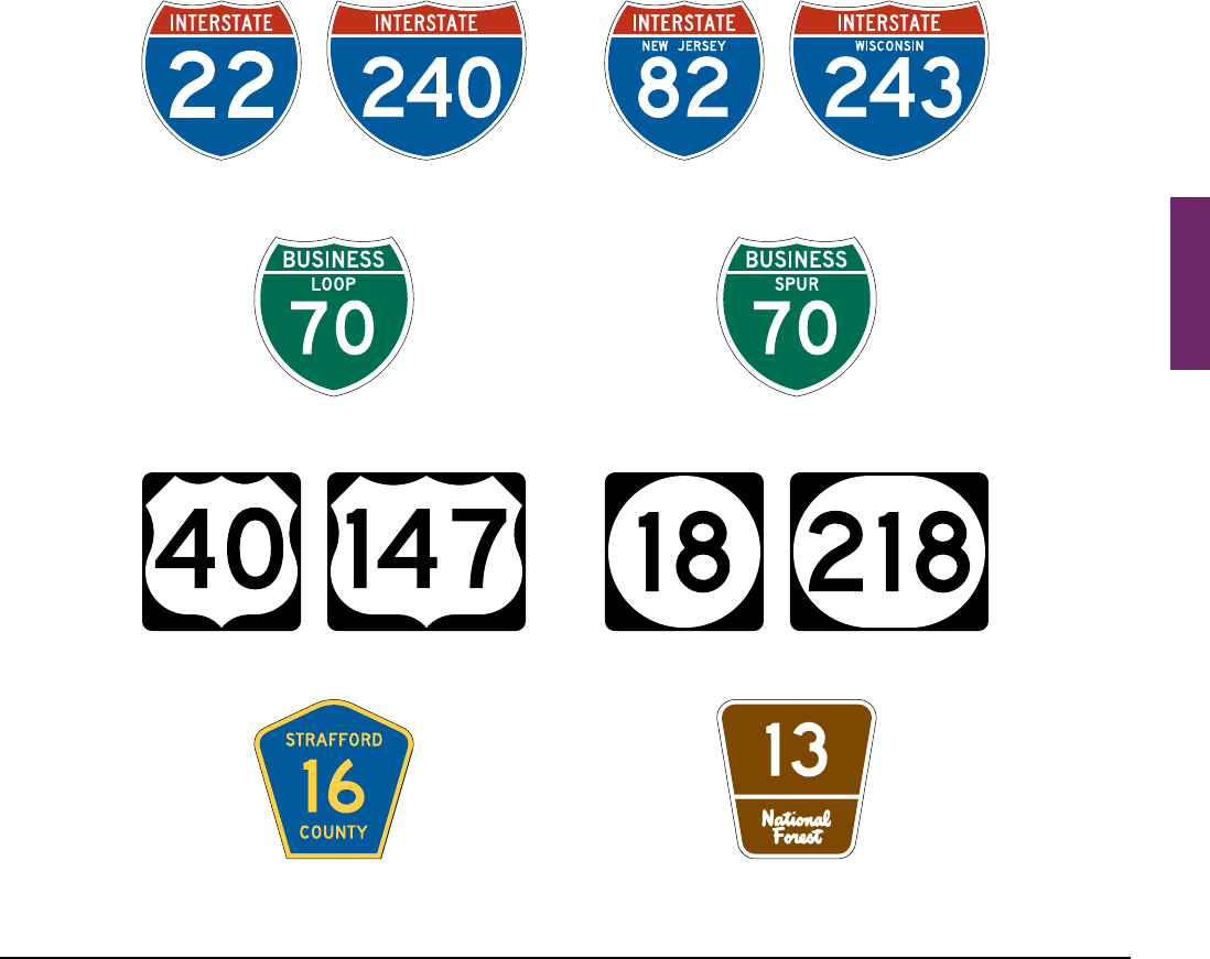
02 Interstate Route (M1-1 and M1-1a) signs (see Figure 2D-4) shall be used on all Interstate routes and in
connection with Route Sign assemblies on intersecting highways.
MUTCD 11th Edition Page 217
Month 2023December 2023
Sect. 2D.11
03 Except as otherwise provided in this Manual, a 24 x 24-inch minimum sign size shall be used for
Interstate route numbers with one or two digits, and a 30 x 24-inch minimum sign size shall be used for
Interstate route numbers having three digits.
Option:
04 WhentheInterstateRoutesignisusedinaRouteSignassembly(seeSection2D.29),theM1-1asign,containing
theStatenameinwhiteupper-caselettersonabluebackgroundasdetailedinthe“StandardHighwaySigns”
publication(seeSection1A.05),maybeusedinplaceoftheM1-1sign.
Standard:
05 Use of the M1-1a sign shall be limited to Route Sign assemblies.
06 Off-Interstate Business Route (M1-2 and M1-3) signs (see Figure 2D-4) shall consist of a cutout shield
displaying the number of the connecting Interstate route and the words BUSINESS and either LOOP
(when the route rejoins the same Interstate route) or SPUR (when the route leaves the corresponding
Interstate route and does not rejoin) in upper-case letters. The legend and border shall be white on a green
background, and the shield shall be the same shape and dimensions as the Interstate Route sign. In no
instance shall the word INTERSTATE appear on the Off-Interstate Business Route sign.
Option:
07 TheOff-InterstateBusinessRoutesignmaybeusedonamajorhighwaythatisnotapartoftheInterstate
system,butonethatservesthebusinessareaofacityfromaninterchangeonthesystem.
Figure 2D-4. Route Signs
Off-Interstate Business Route Sign
M1-2 (Loop)
U.S. Route Sign
M1-4
Interstate Route Sign
M1-1
State Route Sign
M1-5
Forest Route Sign
M1-7
Off-Interstate Business Route Sign
M1-3 (Spur)
Interstate Route Sign
M1-1a
County Route Sign
M1-6

Page 218 MUTCD 11th Edition
Month 2023December 2023
Sect. 2D.11 to 2D.12
Standard:
08 U.S. Route signs (see Figure 2D-4) shall consist of black numerals on a white shield surrounded by a
rectangular black background without a border. This sign shall be used on all U.S. routes and in connection
with Route Sign assemblies on intersecting highways.
09 A 24 x 24-inch minimum sign size shall be used for U.S. route numbers with one or two digits, and a
30 x 24-inch minimum sign size shall be used for U.S. route numbers having three digits.
10 State Route signs shall be designed by the individual State highway agencies.
11 The legend on State Route signs shall conform to the Standard Alphabets contained in the “Standard
Highway Signs” publication (see Section 1A.05).
Guidance:
12 State Route signs (see Figure 2D-4) should be rectangular and should be approximately the same size as
the U.S. Route sign. State Route signs should also be similar to the U.S. Route sign by containing approximately
the same size black numerals on a white area surrounded by a rectangular black background without a border,
and should be devoid of complex graphics. The shape of the white area should be circular in the absence of any
determination to the contrary by the individual State concerned.
13 Where U.S. or State Route signs are used as components of guide signs, only the distinctive shape of
the shield itself and the route numerals within should be used. The rectangular background upon which the
distinctive shape of the shield is mounted, such as the black area around the outside of the shields on the M1-4
and standard M1-5 signs, should not be included on the guide sign. Where U.S. or State Route signs are used as
components of other signs of non-contrasting background colors, the rectangular background should be used so
that recognition of the distinctive shape of the shield can be maintained.
Standard:
14 If county road authorities elect to establish and identify a special system of important county roads, a
statewide policy for such signing shall be established that includes a uniform numbering system to uniquely
identify each route. The County Route (M1-6) sign (see Figure 2D-4) shall consist of a pentagon shape with
a yellow county name and route number and border on a blue background. County Route signs shall be a
minimum size of 24 x 24 inches.
15 If a jurisdiction uses letters instead of numbers to identify routes, all references to numbered routes in
this Chapter shall be interpreted to also include lettered routes.
Guidance:
16 If used with other route signs in common assemblies, the County Route sign should be of a size compatible
with that of the other route signs.
Standard:
17 The design of the National Forest Route (M1-7) sign (see Figure 2D-4) shall be as detailed in the
“Standard Highway Signs” publication (see Section 1A.05). Route signs for other park and forest roads
shall be designed with an appropriate level of distinctiveness and adequate legibility, but in general
compliance with the design principles for route signs and of a size compatible with other route signs used
in common assemblies.
Section 2D.12 Design of Route Sign Auxiliary Plaques
Standard:
01 Route sign auxiliary plaques displaying word legends, except the Junction (M2-1P) auxiliary plaque,
shall have a minimum standard size of 24 x 12 inches. The Junction auxiliary plaque and those auxiliary
plaques displaying arrows shall have a minimum standard size of 21 x 15 inches. All route sign auxiliary
plaques shall match the color combination of the route sign that they supplement.
Guidance:
02 The background, legend, and border of a route sign auxiliary plaque should have the same colors as those
of the route sign with which the auxiliary plaque is mounted in a Route Sign assembly (see Section 2D.29). For a
route sign design that uses multiple background colors, such as the Interstate Route sign, the background color of
the corresponding auxiliary plaque should be that of the background area on which the route number is placed
on the route sign.
Option:
03 Aroutesignandanyauxiliaryplaquesusedwithitmaybecombinedonasinglesignasaguidesign.
MUTCD 11th Edition Page 219
Month 2023December 2023
Sect. 2D.12 to 2D.15
Standard:
04 If a route sign and its auxiliary plaques are combined to form a single guide sign, the background color
of the sign shall be green and the design shall comply with the basic principles for the design of guide signs.
The auxiliary messages shall be white legends placed directly on the green background. Auxiliary plaques
shall not be mounted directly to a guide sign or other type of sign.
Support:
05 Chapter2Fcontainsinformationregardingauxiliaryplaquesfortollhighways.
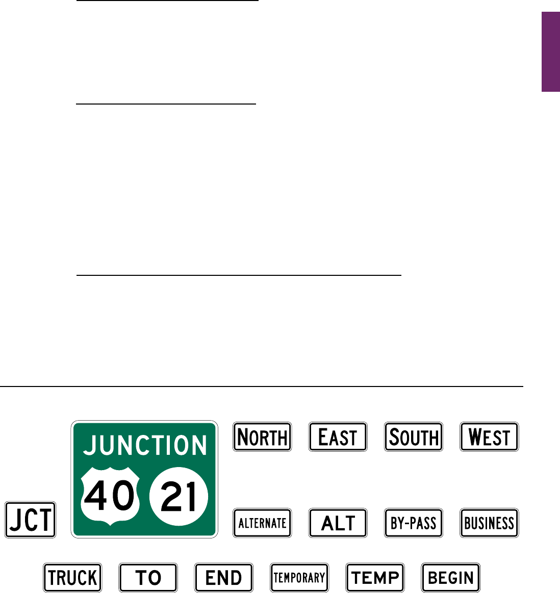
Section 2D.13 Junction Auxiliary Plaque (M2-1P)
Standard:
01 The Junction (M2-1P) auxiliary plaque (see Figure 2D-5) shall display the abbreviated legend JCT
and shall be mounted at the top of an assembly (see Section 2D.30) directly above the route sign, the sign
for an alternative route (see Section 2D.17) that is part of the route designation, or the Cardinal Direction
auxiliary plaque where access is available only to one direction of the intersected route. The minimum size
of the Junction auxiliary plaque shall be 21 x 15 inches for compatibility with auxiliary plaques displaying
arrow symbols.
Section 2D.14 Combination Junction Sign (M2-2)
Option:
01 AsanalternativetothestandardJunctionassemblywheremorethanonerouteistobeintersectedorjoined,a
rectangularguidesignmaybeuseddisplayingthewordJUNCTIONabovetheroutenumbers.
Standard:
02 The Combination Junction (M2-2) sign (see Figure 2D-5) shall have a green background with white
border and lettering for the word JUNCTION.
Guidance:
03 The Combination Junction sign should comply with the specic provisions of Section 2D.11 regarding the
incorporation of the route signs as components of guide signs.
04 Although the size of the Combination Junction sign will depend on the number of routes involved, the
numerals should be large enough for clear legibility and should be of a size comparable with those in the
individual route signs.
Section 2D.15 Cardinal Direction Auxiliary Plaques (M3-1P through M3-4P)
Guidance:
01 Cardinal Direction auxiliary plaques (see Figure 2D-5) displaying the legend NORTH, EAST, SOUTH, or
WEST should be used to indicate the general direction of the entire route.
Standard:
02 To improve the readability and recognition of the cardinal directions, the rst letter of the cardinal
direction words shall be ten percent larger, rounded up to the nearest whole number size.
03 If used, the Cardinal Direction auxiliary plaque shall be mounted directly above a route sign or, if used,
an auxiliary plaque for an alternative route.
M3-2P M3-3P
Figure 2D-5. Route Sign Auxiliary Plaques and Combination Junction Sign
M3-4P
M4-1P M4-1aP M4-2PM2-1P
M3-1P
M4-3P
M4-4P M4-5P M4-6P M4-7P M4-7aP M4-14P
M2-2

Page 220 MUTCD 11th Edition
Month 2023December 2023
Section 2D.16 Alternative Route Auxiliary Plaques (M4-1P through M4-4P)
Option:
01 Alternative Route auxiliary plaques (see Figure 2D-5) displaying legends such as ALTERNATE, BY-PASS,
BUSINESS,orTRUCK,maybeusedtoindicateanalternaterouteofthesamenumberbetweentwopointson
that route.
Standard:
02 If used, the Alternative Route auxiliary plaques shall be mounted directly above a route sign.
Section 2D.17 ALTERNATE Auxiliary Plaques (M4-1P and M4-1aP)
Option:
01 The ALTERNATE (M4-1P) or the ALT (M4-1aP) auxiliary plaque (see Figure 2D-5)maybeusedtoindicate
anofciallydesignatedalternateroutingofanumberedroutebetweentwopointsonthatroute.
Standard:
02 If used, the ALTERNATE or ALT auxiliary plaque shall be mounted directly above a route sign.
03 The M4-1P series plaques shall not be used to sign an alternative routing that is not ofcially designated
and incorporated into the numbered highway system, such as alternative routings for incident management
or emergency detours.
Guidance:
04 The shorter (time or distance) or better-constructed route should retain the regular route number, and the
longer or worse-constructed route should be designated as the alternate route.
Section 2D.18 BY-PASS Auxiliary Plaque (M4-2P)
Option:
01 The BY-PASS (M4-2P) auxiliary plaque (see Figure 2D-5)maybeusedtodesignatearoutethatbranches
fromthenumberedroutethroughacity,bypassesapartofthecityorcongestedarea,andrejoinsthenumbered
route beyond the city.
Standard:
02 If used, the BY-PASS auxiliary plaque shall be mounted directly above a route sign.
Section 2D.19 BUSINESS Auxiliary Plaque (M4-3P)
Option:
01 TheBUSINESS(M4-3P)auxiliaryplaque(seeFigure 2D-5)maybeusedtodesignateanalternateroutethat
branchesfromanumberedroute,passesthroughthebusinessportionofacity,andrejoinsthenumberedroute
beyond that area.
Standard:
02 If used, the BUSINESS auxiliary plaque shall be mounted directly above a route sign.
Section 2D.20 TRUCK Auxiliary Plaque (M4-4P)
Option:
01 The TRUCK (M4-4P) auxiliary plaque (see Figure 2D-5)maybeusedtodesignateanalternateroutethat
branchesfromanumberedroute,whenitisdesirabletoencourageorrequirecommercialvehiclestousethe
alternate route.
Standard:
02 If used, the TRUCK auxiliary plaque shall be mounted directly above a route sign.
Section 2D.21 TO Auxiliary Plaque (M4-5P)
Option:
01 The TO (M4-5P) auxiliary plaque (see Figure 2D-5)maybeusedtoprovidedirectionalguidancetoa
particularroadfacilityfromotherhighwaysinthevicinity(seeSection2D.34).
Standard:
02 If used, the TO auxiliary plaque shall be mounted directly above a route sign or an auxiliary plaque
for an alternative route. If a Cardinal Direction auxiliary plaque is also included in the assembly, the TO
auxiliary plaque shall be mounted directly above the Cardinal Direction auxiliary plaque.
Sect. 2D.16 to 2D.21

MUTCD 11th Edition Page 221
Month 2023December 2023
Sect. 2D.22 to 2D.26
Section 2D.22 END Auxiliary Plaque (M4-6P)
Guidance:
01 The END (M4-6P) auxiliary plaque (see Figure 2D-5) should be used where the route being traveled ends,
usually at a junction with another route.
Standard:
02 If used, the END auxiliary plaque shall be mounted either directly above a route sign or above a sign
for an alternative route that is part of the designation of the route being terminated.
Section 2D.23 BEGIN Auxiliary Plaque (M4-14P)
Option:
01 TheBEGIN(M4-14P)auxiliaryplaque(seeFigure 2D-5)maybeusedwherearoutebegins,usuallyata
junctionwithanotherroute.
Standard:
02 If used, the BEGIN auxiliary plaque shall be mounted at the top of the rst Conrming assembly
(see Section 2D.33) for the route that is beginning.
Guidance:
03 If a BEGIN auxiliary plaque is included in the rst Conrming assembly, a Cardinal Direction auxiliary
plaque should also be included in the assembly.
Standard:
04 If a Cardinal Direction auxiliary plaque is also included in the assembly, the BEGIN auxiliary plaque
shall be mounted directly above the Cardinal Direction auxiliary plaque.
Section 2D.24 TEMPORARY Auxiliary Plaques (M4-7P and M4-7aP)
Option:
01 The TEMPORARY (M4-7P) or the TEMP (M4-7aP) auxiliary plaque (see Figure 2D-5)maybeusedforan
interimperiodtodesignateasectionofhighwaythatisnotplannedasapermanentpartofanumberedroute,but
thatconnectscompletedportionsofthatroute.
Standard:
02 If used, the TEMPORARY or TEMP auxiliary plaque shall be mounted directly above the route sign,
above a Cardinal Direction auxiliary plaque, or above an auxiliary plaque for an alternate route that is a
part of the route designation.
03 TEMPORARY or TEMP auxiliary plaques shall be promptly removed when the temporary route is
abandoned.
Section 2D.25 Temporary Detour Signs and Auxiliary Plaques
Support:
01 Chapter6FcontainsinformationregardingTemporaryDetoursignsandauxiliaryplaques.
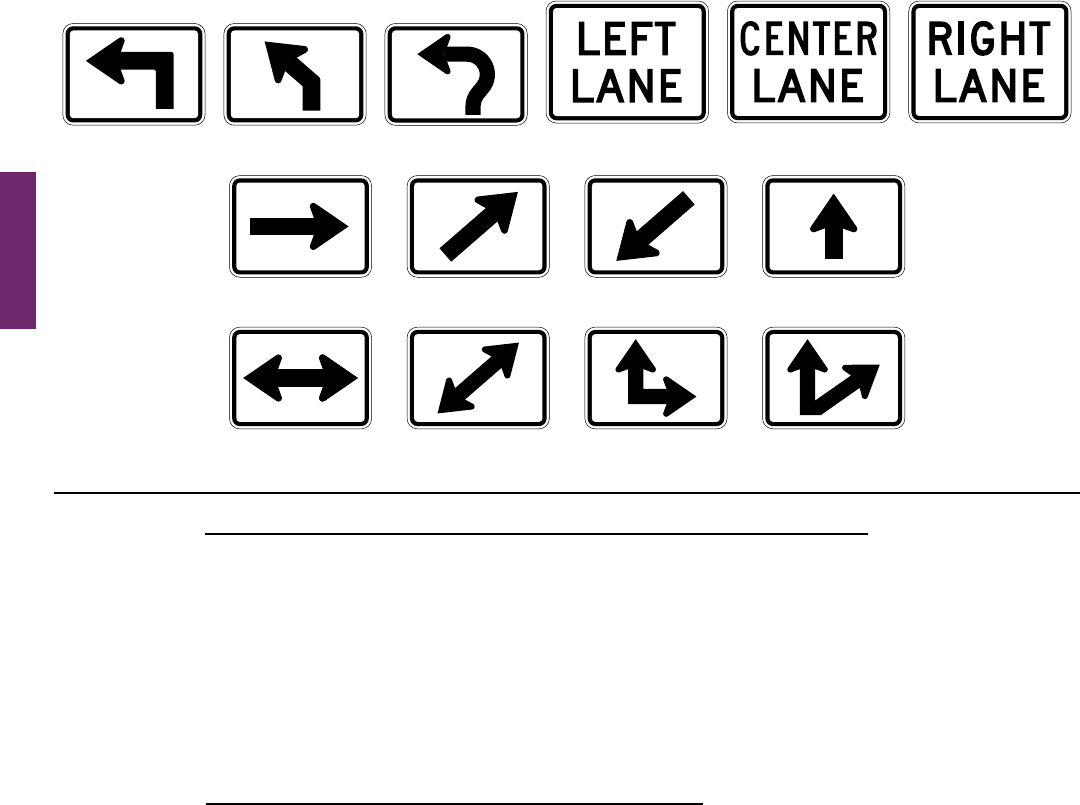
Section 2D.26 Advance Turn Arrow Auxiliary Plaques (M5-1P, M5-2P, and M5-3P)
Standard:
01 If used, the Advance Turn Arrow auxiliary plaque (see Figure 2D-6) shall be mounted directly below
the route sign in Advance Route Turn assemblies, and shall display a right or left arrow, the shaft of which
is bent at a 90-degree angle (M5-1P) or at an oblique angle (M5-2P).
02 If used, the Circular Intersection Advance Turn Arrow (M5-3P) auxiliary plaque (see Figure 2D-6)
shall be used only on the approach to a circular intersection to depict a movement along the circulatory
roadway around the central island and to the left, relative to the approach roadway and entry into
the intersection.
Guidance:
03 If the M5-3P plaque is used, then this arrow type should also be used consistently on any regulatory lane-
use signs (see Chapter 2B), Destination signs (see Section 2D.36), and pavement markings (see Part 3) for a
particular destination or movement.
Page 222 MUTCD 11th Edition
Month 2023December 2023
Sect. 2D.27 to 2D.28
Section 2D.27 Lane Designation Auxiliary Plaques (M5-4P, M5-5P, and M5-6P)
Option:
01 A Lane Designation (M5-4P, M5-5P, or M5-6P) auxiliary plaque (see Figure 2D-6)maybemounteddirectly
belowtheroutesigninanAdvanceRouteTurnassemblyonmulti-laneroadwaystoallowroaduserstomoveinto
the appropriate lane prior to reaching the intersection or interchange.
Standard:
02 If used, the Lane Designation auxiliary plaques shall be used only where the designated lane is a
mandatory movement lane and shall be located adjacent to the full-width portion of the mandatory
movement lane. The Lane Designation auxiliary plaques shall not be installed adjacent to a through lane
in advance of a lane that is being added or along the taper for a lane that is being added.
Section 2D.28 Directional Arrow Auxiliary Plaques (M6 Series)
Standard:
01 If used, the Directional Arrow auxiliary plaque (see Figure 2D-6) shall be mounted below the route
sign and any other auxiliary plaques in Directional assemblies (see Section 2D.32), and shall display a
single-headed or double-headed arrow pointing in the general direction that the route follows.
02 A Directional Arrow auxiliary plaque that displays a double-headed arrow shall not be mounted in any
Directional assembly in advance of or at a circular intersection.
Option:
03 Thediagonaldownward-pointingarrowauxiliary(M6-2aP)plaquemaybeusedinaDirectionalassemblyat
thefarcornerofanintersectiontoindicatetheimmediateentrypointtoafreewayorexpresswayentranceramp
(see Section 2D.50).
Standard:
04 The M6-2aP plaque shall not be used on the approach to or on the near side of an intersection, such as
to designate an approach lane.
Figure 2D-6. Advance Turn and Directional Arrow Auxiliary Plaques
M6-1P
M6-2P M6-2aP M6-3P
M6-4P M6-5P
M6-6P M6-7P
M5-1P M5-2P M5-5P
M5-6P
M5-3P
M5-4P

MUTCD 11th Edition Page 223
Month 2023December 2023
SIGN ASSEMBLIES
Section 2D.29 Route Sign Assemblies
Standard:
01 A Route Sign assembly shall consist of a route sign and auxiliary plaques that further identify the route
and indicate the direction. Except as provided in Paragraph 9 of this Section, Route Sign assemblies shall be
installed on all approaches to numbered routes that intersect with other numbered routes.
02 Where two or more routes follow the same section of highway, the route signs for Interstate, U.S., State,
and county routes shall be mounted in that order from the left in horizontal arrangements and from the top
in vertical arrangements. Subject to this order of precedence, route signs for lower-numbered routes shall
be placed at the left or top.
03 Within groups of assemblies, information for routes intersecting from the left shall be mounted at the
left in horizontal arrangements and at the top or center of vertical arrangements. Similarly, information
for routes intersecting from the right shall be at the right or bottom, and for straight-through routes at the
center in horizontal arrangements or top in vertical arrangements.
04 Route Sign assemblies shall be mounted in accordance with the general specications for signs
(Chapter 2A), with the lowest sign in the assembly at the height prescribed for single signs.
Guidance:
05 Assemblies for two or more routes, or for different directions on the same route, should be mounted in groups
on a common support.
06 Where more than four route signs would be needed in a single Advance Route Turn or Directional assembly,
the route signs should instead be mounted in a guide sign to minimize the need for repetition of the same
information on multiple Cardinal Direction and Directional Arrow auxiliary plaques (see Figure 2D-7).
Option:
07 RouteSignassembliesmaybeinstalledontheapproachestonumberedroutesonunnumberedroadsand
streetsthatcarryanappreciableamountoftrafcdestinedforthenumberedroute.
08 Ifengineeringjudgmentindicatesthatgroupsofassembliesthatincludeoverlappingroutesormultipleturns
mightbeconfusing,routesignsorauxiliarysignsmaybeomittedorcombined,providedthatcleardirectionsare
given to road users.
09 RouteSignassembliesmaybeomittedforroutesthatarepartofanagency’sinternalnumberingsystem,
suchasformaintenanceorotherpurposes,andarenotpubliclymappedorintendedtobeusedfornavigational
purposesbythegeneralpublic.Similarly,numberedroutesthatarenotmaintainedduringcertaintimesofyear,
suchasnotbeingplowedduringwintermonths,maybeomittedfromRouteSignassemblies.
Support:
10 Figure 2D-8showstypicalplacementsofroutesigns.
Section 2D.30 Junction Assembly
Standard:
01 A Junction assembly shall consist of a Junction auxiliary plaque (see Section 2D.13) and a route sign.
The route sign shall display the number of the intersected or joined route.
02 The Junction assembly shall be installed in advance of every intersection where a numbered route is
intersected or joined by another numbered route.
Guidance:
03 In urban areas, the Junction assembly should be installed in the block preceding the intersection. In urban
areas where speeds are low, the Junction assembly should not be installed more than 300 feet in advance of the
intersection.
04 In rural areas, the Junction assembly should be installed at least 400 feet in advance of the intersection. In
rural areas, the minimum distance between a Junction assembly and either a Destination sign or an Advance
Route Turn assembly should be 200 feet.
05 Where speeds are high, greater spacings should be used.
Option:
06 Wheretwoormoreroutesaretobeindicated,asingleJunctionauxiliaryplaquemaybeusedfortheassembly
andallroutesignsgroupedinasinglemounting,oraCombinationJunction(M2-2)sign(seeSection2D.14)
maybeused.
Sect. 2D.29 to 2D.30
Page 224 MUTCD 11th Edition
Month 2023December 2023
Sect. 2D.30
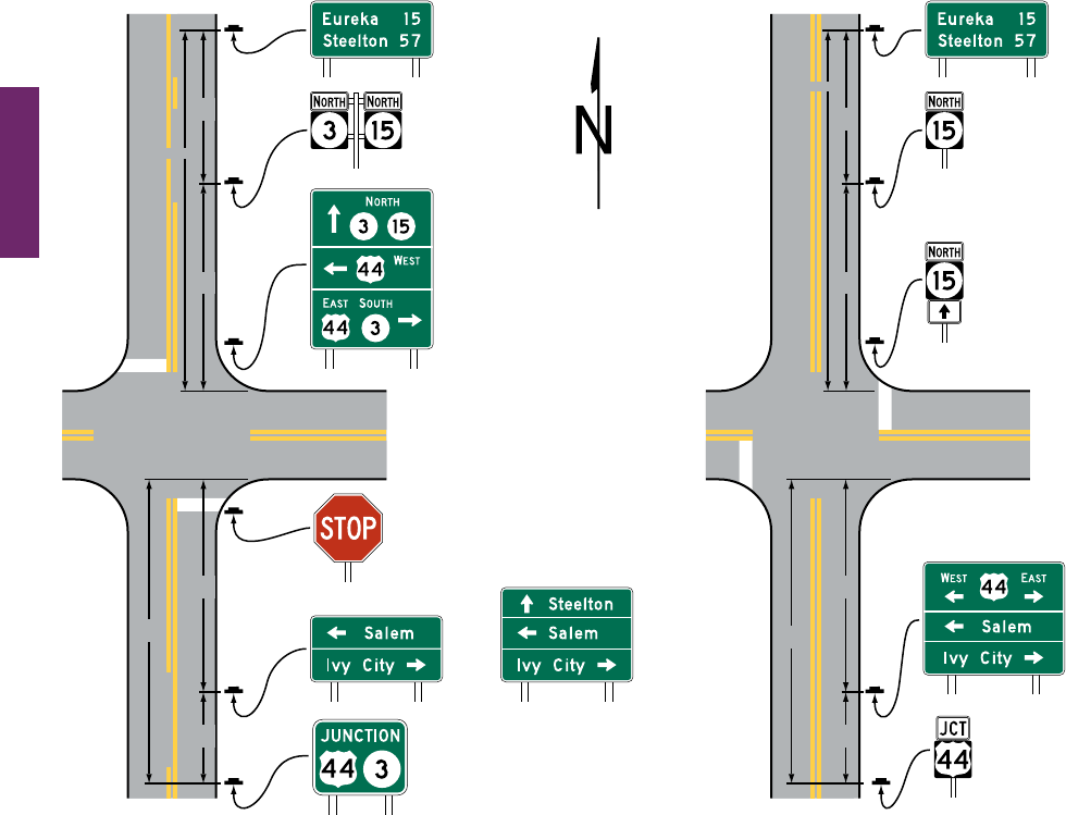
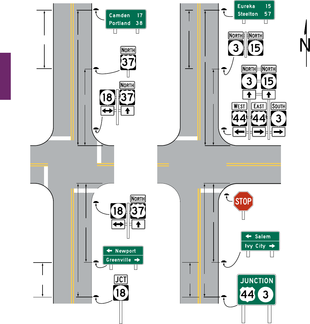
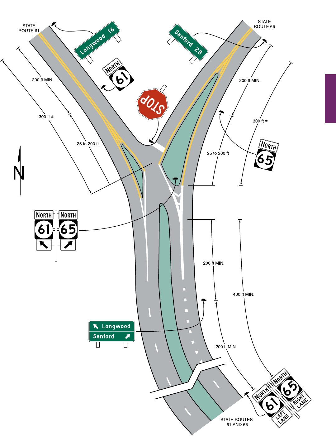
Figure 2D-7. Examples of Consolidation of Route Sign
Assemblies into Guide Signs (Sheet 1 of 2)
A – Minor roadway approach to
a stop-controlled intersection
STATE ROUTES 3 & 15
STATE ROUTE 15
STATE ROUTE 15
STATE ROUTE 15
B – Major roadway approach or approach
to a signalized intersection
OR
200 ft
MIN.
200 ft
MIN.
400 ft
MIN.
25 to
200 ft
100 to
200 ft
200 ft
MIN.
25 to
200 ft
300 ft ±
200 ft
MIN.
400 ft
MIN.
100 to
200 ft
US ROUTE 44 US ROUTE 44 US ROUTE 44 US ROUTE 44
STATE ROUTE 3
(optional)
Destination
guide sign
D1-2
D1-3
Destination
guide sign
D2-2 (optional)
D2-2 (optional)
Confirming
assembly
(optional)
Confirming
assembly
(optional)
Directional
assembly
Junction
assembly
M2-2
Notes:
1. Only one direction of travel and associated signs shown.
2. The spacings shown on this figure are for rural intersections.
See Sections 2D.29, 2D.30, 2D.31, 2D.32, 2D.33, 2D.42,
and 2D.44 for low-speed and/or urban conditions.
300 ft ±
MUTCD 11th Edition Page 225
Month 2023December 2023
Sect. 2D.30
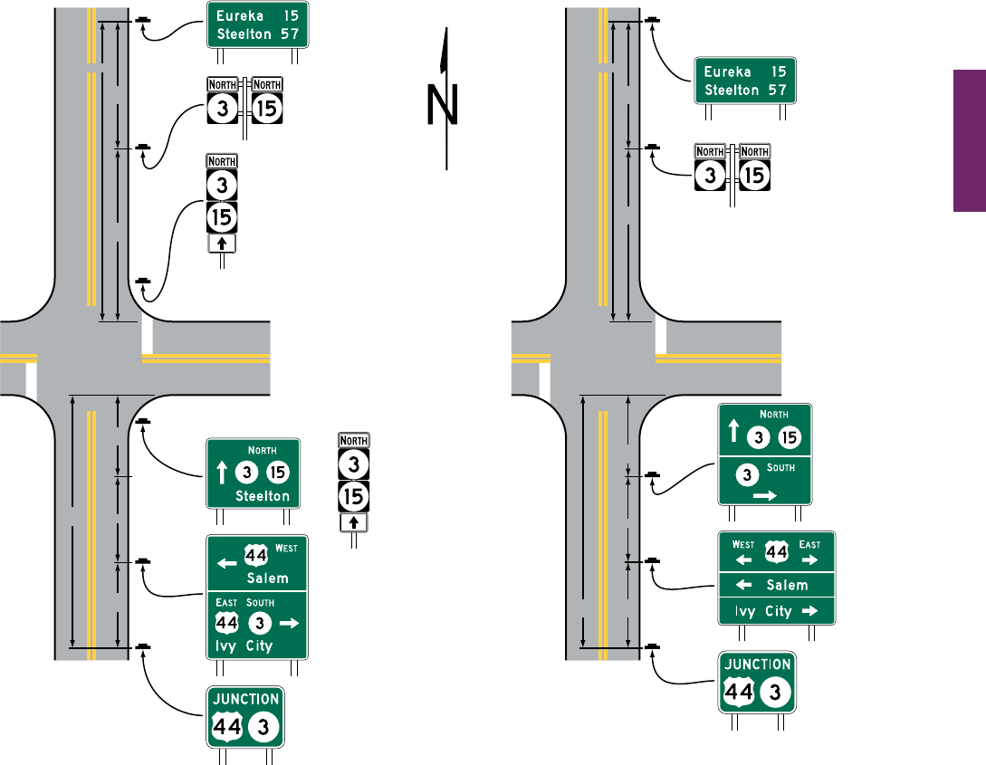
Figure 2D-7. Examples of Consolidation of Route Sign
Assemblies into Guide Signs (Sheet 2 of 2)
C – Major roadway approach or approach to a signalized intersection
where overlapping routes join or separate
STATE ROUTES 3 & 15
STATE ROUTES 3 & 15
STATE ROUTE 15
STATE ROUTE 15
200 ft
MIN.
200 ft
MIN.
450 ft
MIN.
25 to
200 ft
50 to
100 ft
200 ft
300 ft ±
200 ft
MIN.
25 to
200 ft
300 ft ±
200 ft
MIN.
400 ft
MIN.
100 to
200 ft
US ROUTE 44 US ROUTE 44 US ROUTE 44 US ROUTE 44
STATE ROUTE 3 STATE ROUTE 3
D2-2 (optional)
D2-2 (optional)
Confirming
Assembly
(optional)
Confirming
Assembly
(optional)
Directional
Assembly
(optional)
Directional
Assembly
Destination
Guide Sign
Destination
Guide Sign
Destination
Guide Sign
Destination
Guide Sign
M2-2
M2-2
OR
OR
200 ft
Notes:
1. Only one direction of travel and associated signs shown.
2. The spacings shown on this figure are for rural intersections.
See Sections 2D.29, 2D.30, 2D.31, 2D.32, 2D.33, 2D.42,
and 2D.44 for low-speed and/or urban conditions.
Page 226 MUTCD 11th Edition
Month 2023December 2023
Sect. 2D.30
Figure 2D-8. Illustration of Directional Assemblies and Other Route Signs (Sheet 1 of 4)
U.S. ROUTE 44 U.S. ROUTE 44
25 to
200 ft
TRAFFIC
SIGNAL
25 to
200 ft
Directional
assembly
(enlarged, if necessary)
U.S. ROUTE 37
300 ft
±
STATE ROUTES 3 & 15
D2-2
(optional)
D2-2
(optional)
Confirming
assembly
(optional)
Confirming
assembly
(optional)
Additional
directional
assembly
(optional)
Directional
assembly
Junction
assembly
D1-2
D1-2
M2-2
R1-1
STATE ROUTE 18
STATE ROUTE 18
STATE ROUTE 3
100 to
200 ft
400 ft
MIN.
STATE ROUTE 15
U.S. ROUTE 37
100 to
200 ft
400 ft
MIN.
200 ft
MIN.
200 ft
MIN.
200 ft
MIN.
200 ft
MIN.
300 ft
±
Notes:
1. Only the signs associated with the northbound direction of
travel are shown on this figure.
2. The spacings shown on this figure are for rural intersections.
See Sections 2D.29, 2D.30, 2D.31, 2D.32, 2D.33, 2D.42, and
2D.44 for low-speed and/or urban conditions.

MUTCD 11th Edition Page 227
Month 2023December 2023
Sect. 2D.30
Figure 2D-8. Illustration of Directional Assemblies and Other Route Signs (Sheet 2 of 4)
U.S. ROUTE 46STATE ROUTE 8
STATE ROUTE 41
U.S. ROUTE 46
STATE ROUTES
8 AND 15
25 to
200 ft
25 to
200 ft
Directional
assembly
(enlarged,
if necessary)
Advance
route turn
assembly
Directional
assembly
Junction
assembly
Junction
assembly
Confirming
assembly
(optional)
Confirming
assembly
(optional)
D2-2
(optional)
R1-1
D2-2
(optional)
D1-2
D1-2
U.S. ROUTE 56
STATE ROUTE 15
200 ft
MIN.
200 ft
MIN.
200 ft
MIN.
200 ft
MIN.
200 ft
MIN.
U.S. ROUTE 56
400 ft
MIN.
400 ft
MIN.
200 ft
MIN.
300 ft
MIN.
300 ft
±
300 ft
±
200 ft
MIN.
Notes:
1. Only the signs associated with the northbound direction of
travel are shown on this figure.
2. The spacings shown on this figure are for rural intersections.
See Sections 2D.29, 2D.30, 2D.31, 2D.32, 2D.33, 2D.42, and
2D.44 for low-speed and/or urban conditions.
Page 228 MUTCD 11th Edition
Month 2023December 2023
Sect. 2D.30
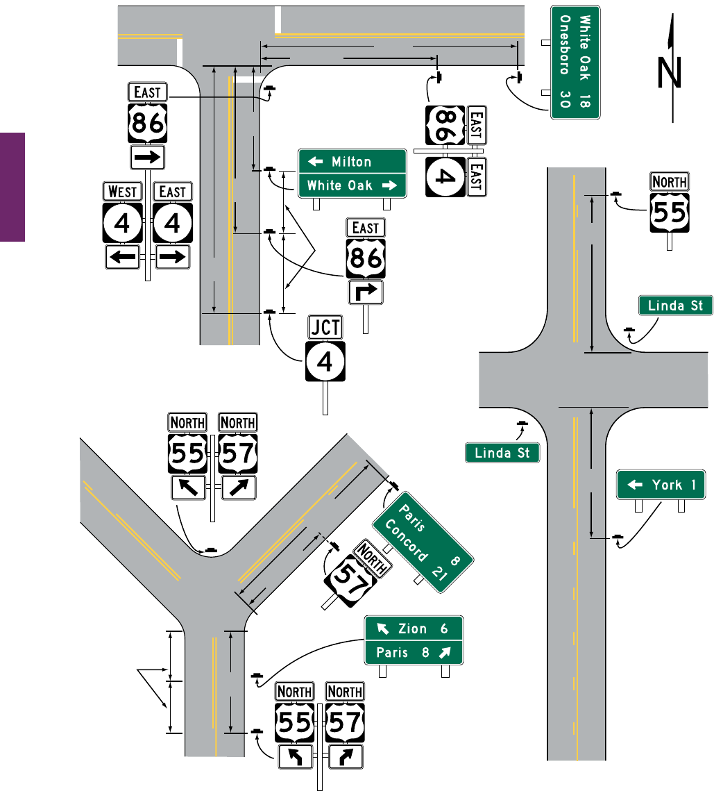
Figure 2D-8. Illustration of Directional Assemblies and Other Route Signs (Sheet 3 of 4)
25 to 200 ft
25 to 200 ft
25 to
200 ft
TRAFFIC
SIGNAL
Directional assembly
(enlarged, if necessary)
Directional
assembly
Junction
assembly
Advance
route turn
assembly
Advance
route turn
assembly
Confirming
assembly
(optional)
Confirming
assembly
(optional)
Destination
guide sign
Confirming
assembly
(optional)
D1-2
D3-1
D3-1
D2-2
(optional)
D1-1
D2-2
(optional)
STATE ROUTE 4
U.S. ROUTE 86
STATE ROUTE 4
600 ft
MIN.
200 ft
MIN.
400 ft
MIN.
200 ft
MIN.
U.S. ROUTE 86
U.S. ROUTE 55
LINDA ST
200 ft
MIN.
U.S. ROUTE 55
U.S. ROUTES 55
AND 57
400 ft
MIN.
U.S. ROUTE 55
U.S. ROUTE 57
300 ft
±
200 ft
MIN.
300 ft
±
Notes:
1. Only the signs associated with the northbound direction of
travel are shown on this figure.
2. The spacings shown on this figure are for rural intersections.
See Sections 2D.29, 2D.30, 2D.31, 2D.32, 2D.33, 2D.42, and
2D.44 for low-speed and/or urban conditions.
MUTCD 11th Edition Page 229
Month 2023December 2023
Sect. 2D.30
Figure 2D-8. Illustration of Directional Assemblies and Other Route Signs (Sheet 4 of 4)
Notes:
1. Only the signs associated with the northbound
direction of travel are shown on this figure.
2. The spacings shown on this figure are for rural
intersections. See Sections 2D.29, 2D.30,
2D.31, 2D.32, 2D.33, 2D.42, and 2D.44 for
low-speed and/or urban conditions.
D2-2
(optional)
D2-2
(optional)
Confirming
assembly
(optional)
Advance
route turn
assembly
Confirming
assembly
(optional)
Directional
assembly
Destination
guide sign
R1-1

Page 230 MUTCD 11th Edition
Month 2023December 2023
Sect. 2D.31 to 2D.32
Section 2D.31 Advance Route Turn Assembly
Standard:
01 An Advance Route Turn assembly shall consist of a route sign, an Advance Turn Arrow or word
message auxiliary plaque, and a Cardinal Direction auxiliary plaque, if needed. It shall be installed in
advance of an intersection where a turn must be made to remain on the indicated route.
Option:
02 TheAdvanceRouteTurnassemblymaybeusedtosupplementtherequiredJunctionassemblyinadvanceof
intersecting routes.
Guidance:
03 Where a multi-lane highway approaches an interchange or intersection with a numbered route, the Advance
Route Turn assembly should be used to provide advance notice so that road users know the correct lane(s) from
which to make their turn.
Option:
04 LaneDesignationauxiliaryplaques(seeSection2D.27)maybeusedinAdvanceRouteTurnAssemblies
inplaceoftheAdvanceTurnArrowauxiliaryplaqueswhereengineeringjudgmentindicatesthatspeciclane
informationassociatedwitheachrouteisneededandoverheadsigningisimpracticableandthedesignatedlane
isamandatorymovementlane.AnassemblywiththeLaneDesignationauxiliaryplaquesmaysupplementor
substituteforanassemblywithAdvanceTurnArrowauxiliaryplaques.
Guidance:
05 In low-speed areas, the Advance Route Turn assembly should be installed not less than 200 feet in advance
of the turn. In high-speed areas, the Advance Route Turn assembly should be installed not less than 300 feet in
advance of the turn. In rural areas, the minimum distance between an Advance Route Turn assembly and either
a Destination sign or a Junction assembly should be 200 feet.
Standard:
06 An assembly that includes an Advance Turn Arrow auxiliary plaque shall not be placed where there
is an intersection between it and the designated turn.
Guidance:
07 Sufcient distance should be allowed between the assembly and any preceding intersection that could be
mistaken for the indicated turn.
Section 2D.32 Directional Assembly
Standard:
01 A Directional assembly shall consist of a Cardinal Direction auxiliary plaque, if needed; a route sign; and
a Directional Arrow auxiliary plaque. The uses of Directional assemblies shall comply with the following:
A. Turn movements (indicated in advance by an Advance Route Turn assembly) shall be marked by
a Directional assembly with a route sign displaying the number of the turning route and a single-
headed arrow pointing in the direction of the turn.
B. The beginning of a route (indicated in advance by a Junction assembly) shall be marked by a
Directional assembly with a route sign displaying the number of that route and a single-headed
arrow pointing in the direction of the route.
C. An intersected route (indicated in advance by a Junction assembly) on a crossroad where the route
is designated on both legs shall be designated by:
1. Two Directional assemblies, each with a route sign displaying the number of the intersected
route, a Cardinal Direction auxiliary plaque, and a single-headed arrow pointing in the
direction of movement on that route; or
2. A Directional assembly with a route sign displaying the number of the intersected route and a
double-headed arrow, pointing at appropriate angles to the left, right, or ahead.
D. An intersected route (indicated in advance by a Junction assembly) on a side road or on a crossroad
where the route is designated only on one of the legs shall be designated by a Directional assembly
with a route sign displaying the number of the intersected route, a Cardinal Direction auxiliary
plaque, and a single-headed arrow pointing in the direction of movement on that route.
Guidance:
02 Straight-through movements should be indicated by a Directional assembly with a route sign displaying the
number of the continuing route and a vertical arrow. A Directional assembly should not be used for a straight-
through movement in the absence of other assemblies indicating right or left turns, as the Conrming assembly
sign beyond the intersection normally provides adequate guidance.
MUTCD 11th Edition Page 231
Month 2023December 2023
Sect. 2D.32 to 2D.34
03 Directional assemblies should be located on the near right corner of the intersection. At major intersections
and at Y or offset intersections, additional Directional assemblies should be installed on the far right or left
corner to conrm the near-side assemblies. When the near-corner position is impractical for Directional
assemblies, the far right corner should be the preferred alternative, with oversized signs, if necessary, for
legibility. Where unusual conditions exist, the location of a Directional assembly should be determined by
engineering judgment with the goal being to provide the best possible combination of view and safety.
Support:
04 Itismoreimportantthatguidesignsbereadable,andthattheinformationanddirectiondisplayedthereon
bereadilyunderstood,attheappropriatetimeandplacethantobelocatedwithabsoluteuniformity.
05 Figure 2D-8showstypicalplacementsofDirectionalassemblies.
Section 2D.33 Conrming or Reassurance Assemblies
Standard:
01
If used, Conrming or Reassurance assemblies shall consist of a Cardinal Direction auxiliary plaque
and a route sign. Where the Conrming or Reassurance assembly is for an alternative route, the appropriate
auxiliary plaque for an alternative route (see Section 2D.16) shall also be included in the assembly.
Guidance:
02 A Conrming assembly should be installed just beyond intersections of numbered routes. It should be placed
25 to 200 feet beyond the far shoulder or curb line of the intersected highway.
03 If used, Reassurance assemblies should be installed between intersections in urban areas as needed, and
beyond the built-up area of any incorporated city or town.
04 Route signs for either conrming or reassurance purposes should be spaced at such intervals as necessary
to keep road users informed of their routes.
Section 2D.34 Trailblazer Assembly
Support:
01 Trailblazerassembliesprovidedirectionalguidancetoaparticularroadfacilityfromotherhighwaysinthe
vicinity.ThisguidanceisaccomplishedbyinstallingTrailblazerassembliesatstrategiclocationstoindicatethe
directiontothenearestormostconvenientpointofaccess.TheuseofthewordTOindicatesthattheroador
streetwherethesignispostedisnotapartoftheindicatedroute,andthataroaduserismerelybeingdirected
progressively to the route.
Standard:
02 A Trailblazer assembly shall consist of a TO auxiliary plaque (see Section 2D.21), a route sign for a
numbered or named highway (see Section 2D.56) or an identication sign for a byway, historic trail, or
auto tour route sign (see Sections 2D.57 and 2D.58), and a single-headed Directional Arrow auxiliary
plaque pointing in the direction leading to the route. Where the Trailblazer assembly is for an alternative
route, the appropriate auxiliary plaque for an alternative route (see Section 2D.16) shall also be included
in the assembly.
Option:
03 ACardinalDirectionauxiliaryplaque(seeSection2D.15)maybeusedinaTrailblazerassemblywherethe
direction leading to the route provides access only to one direction of travel for that route.
Guidance:
04 The TO auxiliary plaque, Cardinal Direction auxiliary plaque, and Directional Arrow auxiliary plaque
should be of the standard size provided for auxiliary plaques of their respective type. The route sign should be
the size provided in Section 2D.11.
Option:
05 TrailblazerassembliesmaybeinstalledwithotherRouteSignassemblies,oralone,intheimmediatevicinity
of the designated facilities.

Page 232 MUTCD 11th Edition
Month 2023December 2023
Sect. 2D.35 to 2D.36
DESTINATION AND DISTANCE SIGNS
Section 2D.35 Destination and Distance Signs
Support:
01 Inadditiontoguidancebyroutenumbers,itisdesirabletosupplytheroaduserinformationconcerningthe
destinationsthatcanbereachedbywayofnumberedorunnumberedroutes.ThisisdonebymeansofDestination
signs and Distance signs.
Option:
02 RouteshieldsandcardinaldirectionsmaybeincludedontheDestinationsignwiththedestinations
and arrows.
Guidance:
03 If Route shields and cardinal directions are included on a Destination sign, the height of the route shields
should be at least two times the height of the upper-case letters of the principal legend and not less than 18
inches, and the letter height of cardinal directions should be at least the minimum letter height specied for
these signs.
04 If used, destination names on low-volume rural roads should be as specic and descriptive as possible.
Destinations such as campgrounds, ranger stations, and recreational areas should be clearly indicated so that
they are not interpreted to be communities or locations with road user services.
Section 2D.36 Destination Signs (D1 Series)
Standard:
01 Except on approaches to interchanges (see Section 2D.49), the Destination (D1-1 through D1-3) signs
(see Figure 2D-9), if used, shall be a horizontal rectangle displaying the name of a city, town, village, or
other trafc generator, and a directional arrow.
Option:
02 Thedistance(seeSection2D.43)totheplacenamedmayalsobedisplayedontheDestination(D1-1athrough
D1-3a) signs (see Figure 2D-9).Ifseveraldestinationsaretobedisplayedatasinglepoint,theseveralnamesmay
beplacedonasinglesignwithanarrow(andthedistance,ifdesired)foreachname.Ifmorethanonedestination
liesinthesamedirection,asinglearrowmaybeusedforsuchagroupofdestinations.
Guidance:
03 Adequate separation should be made between any destinations or group of destinations in one direction and
those in other directions by suitable design of the arrow, spacing of lines of legend, heavy lines entirely across the
sign, or separate signs.
Support:
04 Separation of destinations by direction by the use of a horizontal separator line can enhance the readability
ofaDestinationsignbyrelatinganarrowanditscorrespondingdestination(s)andbyeliminatingtheneedfor
multiplearrowsthatpointinthesamedirectionandexcessivespacebetweenlinesoflegend.
Standard:
05 Except as otherwise provided in this Manual, an arrow pointing to the right shall be at the extreme
right of the sign, and an arrow pointing left or up shall be at the extreme left. The distance numerals, if
used, shall be placed to the right of the destination names.
Option:
06 Anarrowpointingupmaybeplacedattheextremerightofthesignwhenthesignismountedtotheleftofthe
trafctowhichitapplies.
Guidance:
07 Unless a sloping arrow will convey a clearer indication of the direction to be followed, the directional arrows
should be horizontal or vertical.
08 If several individual name signs are assembled into a group, all signs in the assembly should be of the same
horizontal width.
09 Destination signs should be used:
A. At the intersections of U.S. or State numbered routes with Interstate, U.S., or State numbered routes; and
B. At points where they serve to direct trafc from U.S. or State numbered routes to the business section of
towns, or to other destinations reached by unnumbered routes.
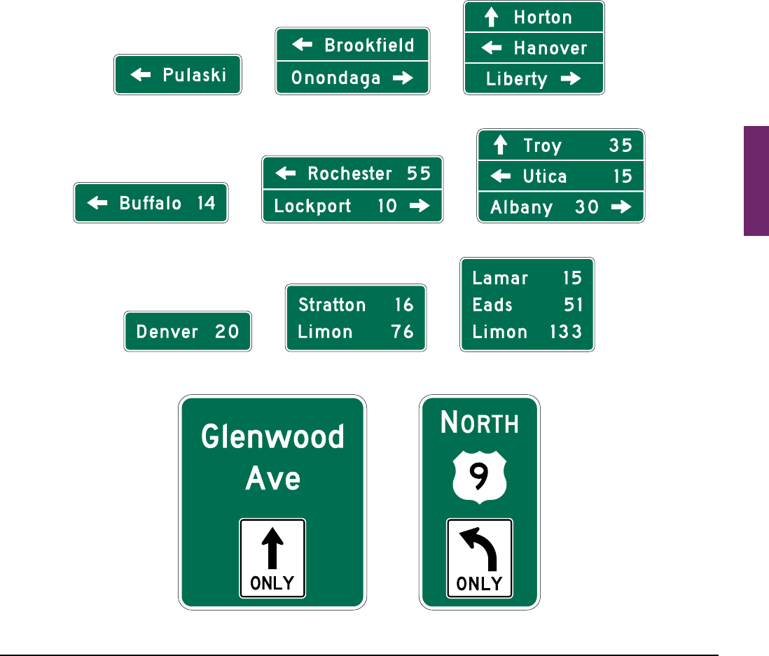
MUTCD 11th Edition Page 233
Month 2023December 2023
Sect. 2D.36
Standard:
10 Where a total of three or fewer destinations are displayed on the Advance guide (see Section 2E.23) and
Supplemental guide (see Section 2E.51) signs, no more than three destination names shall be displayed on
a Destination sign. Where four destinations are displayed on the Advance guide and Supplemental guide
signs, no more than four destination names shall be displayed on a Destination sign.
Guidance:
11 If space permits, four destinations should be displayed on two separate signs at two separate locations.
Option:
12 Where space does not permit, or where all four destinations are in one direction, a single sign may be used.
Where a single sign is used and all destinations are in the same direction, the arrow may be placed below the
destinations for the purpose of enhancing the conspicuity of the arrow.
Standard:
13 Where a single four-name sign assembly is used, a heavy line approximating the width of the sign
border entirely across the sign or separate signs shall be used to separate destinations by direction.
Figure 2D-9. Destination and Distance Signs
D1-2a D1-3aD1-1a
D1-1 D1-2 D1-3
D2-1 D2-2 D2-3
D15-1
OR

Page 234 MUTCD 11th Edition
Month 2023December 2023
Sect. 2D.36 to 2D.37
Guidance:
14 The closest destination lying straight ahead should be at the top of the sign or assembly, and below it the
closest destinations to the left and to the right, in that order. The destination displayed for each direction should
ordinarily be the next county seat or the next principal city, rather than a more distant destination. In the case of
overlapping routes, only one destination should be displayed in each direction for each route.
Standard:
15 If more than one destination is displayed in the same direction, the name of a nearer destination shall be
displayed above the name of a destination that is farther away.
Support:
16 Overheaddestinationguidesignsaresometimeshelpfulonmulti-laneconventionalroadwayswithcomplexor
unusualroadwayalignmentsorgeometricsatintersectinghighwaystoprovidepositivedirectiontodestinations
and to assign lanes to be used for destinations.
Option:
17 OverheadDestinationsignsmaybeusedtoprovidelaneassignmentanddestinationinformationforsome
orallofthelanesontheapproachtoamulti-laneintersection.Destinationinformationmayincludecardinal
directions,routenumbers,streetnames,and/orplacenames.
18 OverheadsignsusingtheArrow-per-Lanesigndesignconguration(seeFigure 2D-10)maybeusedtoprovide
laneassignmentsforsomeoralllanedestinationsattheapproachtoamulti-laneintersection(seeSection2D.37).
Section 2D.37 Overhead Arrow-per-Lane Destination Guide Signs
Support:
01 OverheadArrow-per-Lanedestinationguidesignsaresometimesusedonmulti-laneconventionalroadways
to provide positive direction to destinations and to indicate lanes to be used for those destinations. These locations
typicallyincludecomplexorunusualroadwayalignmentsorgeometrics.OverheadArrow-per-Lanesignson
conventional roads do not always have arrows for every lane. Sheet 2 of Figure 2A-4 and Sheet 1 of Figure 2D-10
showexamplesoftheuseofanOverheadArrow-per-LaneGuidesignonaconventionalroad.UnliketheCombined
Lane-Use/Destination(D15-1)sign(seeSection2D.38),OverheadArrow-per-Lanesignscanbeusedtoprovide
laneassignmentswherethedesignatedlaneisnotamandatorymovementlane.
Option:
02 Atcomplexintersectionapproachesinvolvingmultiplelanesanddestinations,anOverheadArrow-per-
Lanedestinationguidesignmaybeusedtoprovidedestinationinformationforsomeoralllanes.Destination
informationmayincludecardinaldirection,routenumbers,streetnames,and/orplacenames.
Standard:
03 Overhead Arrow-per-Lane signs for conventional roads shall only be used for multi-lane approaches to
intersections that have an option lane.
04 Overhead Arrow-per-Lane guide signs used on conventional roads shall include as a minimum one
arrow above each mandatory turn lane and a bifurcated arrow for the option lane from which both the
through and turning movements are allowed.
Guidance:
05 Displaying an arrow over each through movement lane that does not allow turning should be considered for
providing additional positive guidance.
Standard:
06 Overhead Arrow-per-Lane signs for conventional roads shall be designed in accordance with the
following criteria:
A. The shaft of each arrow shall be located over the approximate center of the lane to which it applies.
B. Arrows for continuing through lanes shall be vertically upward-pointing (see Figure 2D-10).
C. The arrow for a lane that must turn shall be curved in the direction of the turn and shall be
accompanied by a black-on-yellow ONLY (E11-1b) sign panel (see Figure 2E-17) adjacent to the
lower end of the arrow shaft.
D. The arrow for an optional exit lane that also carries the through route shall have a single shaft
that bifurcates into a vertically upward-pointing arrow and a curving arrow corresponding to the
conguration of the through and turn lanes.
E. A vertical white line shall be used to separate the route shields and destinations for the two
diverging movements from each other.
F. The number of lanes displayed on a sign shall correspond to the number of lanes being signed for
at the location of that sign. An advance sign shall not depict lanes that are added downstream of
a sign location.
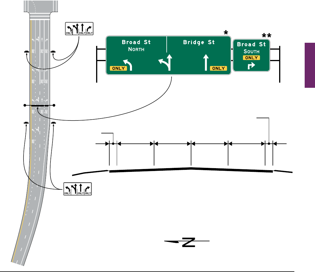
MUTCD 11th Edition Page 235
Month 2023December 2023
Sect. 2D.37
Guidance:
07 Overhead Arrow-per-Lane guide signs used on conventional roads should be designed in accordance with
the following additional criteria:
A. No more than one destination should be displayed for each movement, and no more than three
destinations should be displayed per sign.
B. The arrowhead(s) for the diverging movement should be positioned lower on the sign than the
arrowhead(s) for the movement that continues straight ahead.
C. Route shields, cardinal directions, and destinations should be positioned on the sign such that they are
clearly related to the arrowhead(s) for the movement to which they apply.
D. The vertical white line that is used to separate the route shields and destinations for the two diverging
movements from each other should not descend below the top of the arrowheads for the through lanes,
and should be positioned approximately halfway between the diverging arrowheads for the optional
movement lane.
08 Destination information should be kept to a minimum necessary to provide positive guidance without
overloading the road user.
Figure 2D-10. Examples of Overhead Signs at an Intersection (Sheet 1 of 3)
A – Combination of mandatory and optional movement lanes
Broad
Street
Exit ramp
Shoulder
R3-8 Series
R3-8 Series
Travel
lane
Left
only
Travel
lane
Left or
thru
Travel
lane
Thru
only
Travel
lane
Right
only
Shoulder
* Overhead Arrow-per Lane guide sign only
for destinations that include an optional
movement lane
** Conventional guide sign for destinations with
one or more mandatory movement lanes
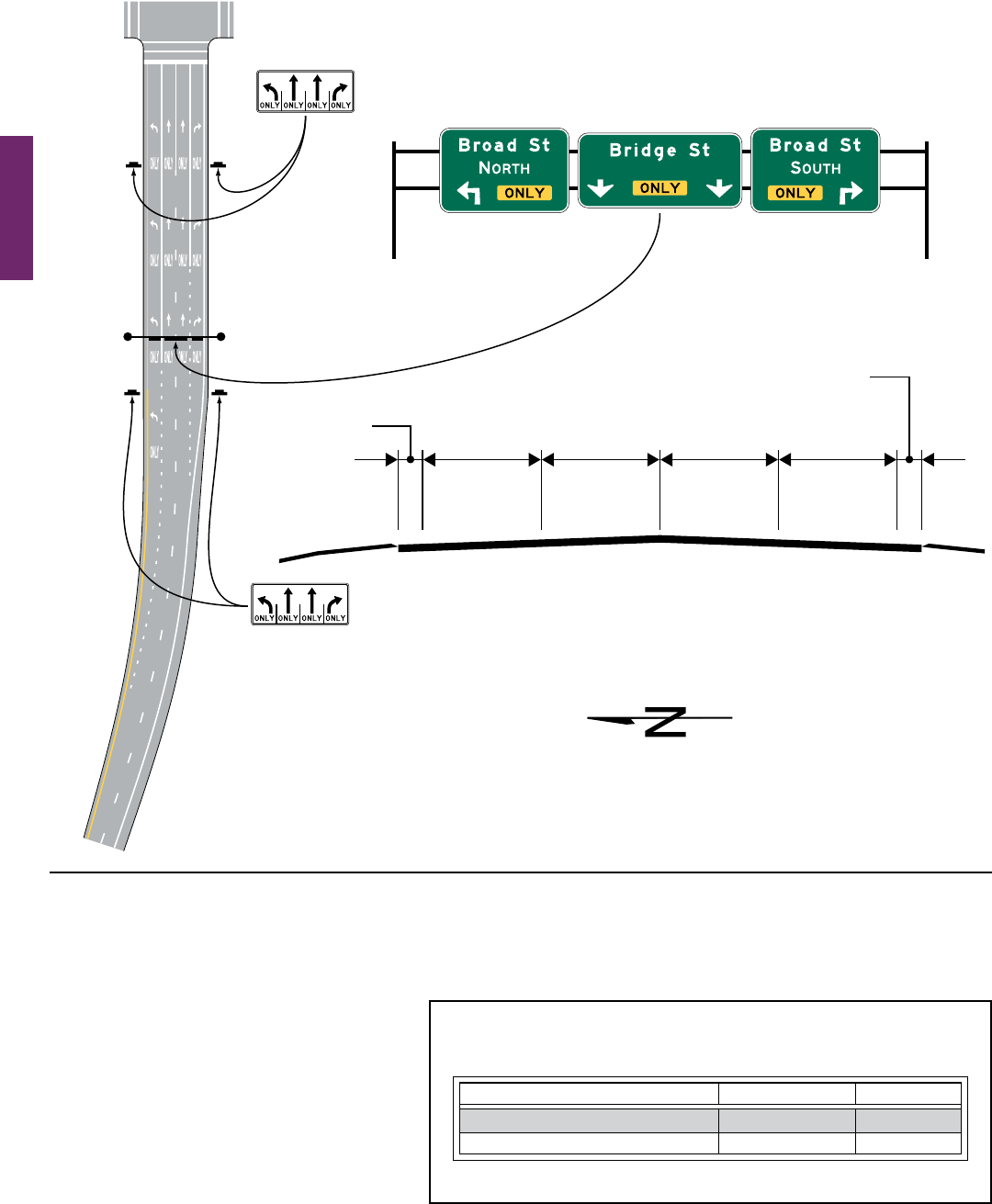
Page 236 MUTCD 11th Edition
Month 2023December 2023
Sect. 2D.37
Standard:
09 The minimum height of arrows on an Overhead Arrow-per-Lane sign used on a conventional road shall
be as shown in Table 2D-5.
Guidance:
10 When letter heights and other sign
legend elements are enlarged there
should be an corresponding increase in
the arrow size used.
Option:
11 Curved-stemarrowsmaybe
substituted on Overhead Arrow-per-
Lanesignsonmulti-laneapproachestoa
circular intersection with an option lane
(see Section 2D.39).
Figure 2D-10. Examples of Overhead Signs at an Intersection (Sheet 2 of 3)
B – Mandatory movement lanes
Broad
Street
Exit ramp
Travel
lane
Left
only
Travel
lane
Thru
only
Travel
lane
Thru
only
Travel
lane
Right
only
Conventional guide signs for all destinations
with one or more mandatory movement lanes
Shoulder
R3-8 Series
R3-8 Series
Shoulder
Table 2D-5. Overhead Arrow-per-Lane Arrow
Height Based on Principal Legend Letter Height
Principal Legend Letter Height Straight Arrow Turn Arrow
10.67 - 13.33 32 24
8 24 18
Note: Letter and arrow heights are shown in inches.

MUTCD 11th Edition Page 237
Month 2023December 2023
Sect. 2D.38
Section 2D.38 Combination Lane-Use/Destination Overhead Guide Sign (D15-1)
Option:
01 Atintersectionapproachesinvolvingmultipleturnlanesanddestinations,aCombinationLane-Use/
Destination (D15-1) overhead guide sign (see Figure 2D-9)thatcombinesalane-useregulatorysignwith
destinationinformationsuchasacardinaldirection,aroutenumber,astreetname,and/oraplacename
maybeused.
Support:
02 Atsuchlocations,thecombinedinformationontheD15-1signscanbeevenmoreeffectivethanseparatelane-
useandguidesignsforconveyingtounfamiliardriverswhichlaneorlanestouseforaparticulardestination.
03 Figure 2D-9showsanexampleofaD15-1signthatcombineslane-useandstreetnameinformationandan
exampleofaD15-1signthatcombineslane-use,cardinaldirection,androutenumberinformation.
Figure 2D-10. Examples of Overhead Signs at an Intersection (Sheet 3 of 3)
C – Mandatory movement lanes with dual turn lanes
Broad
Street
Exit ramp
Travel
lane
Left
only
Travel
lane
Left
only
Travel
lane
Thru
only
Travel
lane
Right
only
Conventional guide signs for all destinations
with one or more mandatory movement lanes
Shoulder
R3-8 Series
R3-8 Series
Shoulder

Page 238 MUTCD 11th Edition
Month 2023December 2023
Sect. 2D.38 to 2D.41
Standard:
04 The Combination Lane-Use/Destination (D15-1) overhead guide sign shall be used only where the
designated lane is a mandatory movement lane. The D15-1 sign shall not be used for lanes with optional
movements.
05 The D15-1 sign shall have a green background with a white border. As shown in Figure 2D-9, the lane-
use sign (see Chapter 2B) shall be placed near the bottom of the sign and the destination information shall
be placed near the top of the sign. The D15-1 sign shall be located over the approximate center of the lane
to which it applies.
Section 2D.39 Destination Signs at Circular Intersections
Standard:
01
Destination signs that are used at circular intersections shall comply with the provisions of Section 2D.36,
except as provided in this Section.
Option:
02 Exit Destination (D1-1d and D1-1e) signs (see Figure 2D-11) with diagonal upward-pointing arrows or
Directionalassemblies(seeSection2D.32)maybeusedtodesignateaparticularexitfromacircularintersection.
03 Destination (D1-2d and D1-3d) signs (see Figure 2D-11)withcurved-stemarrowsmaybeusedonapproaches
tocircularintersectionstorepresenttheleft-turnmovements.
04 Curved-stemarrowsoncircularintersectiondestinationsignsmaypointindiagonaldirectionstodepictthe
location of an exit relative to the approach roadway and entry into the intersection.
05 AnOverheadArrow-per-LaneDestinationsign(seeSection2D.37)withcurved-stemarrowsmaybeusedon
multi-laneapproachestocircularintersectionsthathaveanoption lane.
06 A Destination (D1-5 or D1-5a) sign (see Figure 2D-11)withadiagramofthecircularintersectionmaybeused
on approaches to circular intersections.
Guidance:
07 If curved-stem arrows are used on destination signs, then this arrow type should also be used consistently
on any regulatory lane-use signs (see Chapter 2B), Directional assemblies (see Section 2D.32), and pavement
markings (see Part 3) for a particular destination or movement.
Support:
08 Figure 2D-12showsexamplesofguidesigningforcircularintersections.
09 CircularIntersectionDiagrammatic(D1-5orD1-5a)signsmightbepreferablewherespaceisavailableand
wherethegeometryofthecircularintersectionisnon-typical,suchaswheremorethanfourlegsarepresentor
wherethelegsarenotatapproximately90-degreeanglestoeachother.Insuchcases,minimizingtheamountof
legend for each destination and designing the sign so that the arrows for each destination clearly align with the
roadwaygeometrywillaidroaduserunderstandingofthesignandnavigationthroughthearea.
Standard:
10 If used, the Circular Intersection Diagrammatic signs shall not depict the number of lanes within the
circulatory roadway of the intersection, or on its approaches or exits, through the use of lane lines, multiple
arrow shafts for the same movement, or other methods.
Support:
11 Chapter2Bcontainsinformationregardingregulatorysignsatcircularintersections,Chapter2Ccontains
informationregardingwarningsignsatcircularintersections,andChapter3Dcontainsinformationregarding
pavementmarkingsatcircularintersections.
Section 2D.40 Destination Signs at Jughandles
Standard:
01 Destination signs that are used at jughandles shall comply with the provisions of Section 2D.36.
Support:
02 Section2B.35containsinformationregardingregulatorysignsforjughandleturns.Figure2B-9shows
examplesofregulatoryanddestinationguidesigningforvarioustypesofjughandleturns.
Section 2D.41 Destination Signs at Intersections with Indirect Turning Movements
Guidance:
01 A system of guide signs along with associated lane markings should be used to direct trafc through
intersections with indirect turning movements.
Support:
02 Figure 2D-13showsexamplesofdestinationguidesigningforintersectionswithindirectturningmovements.
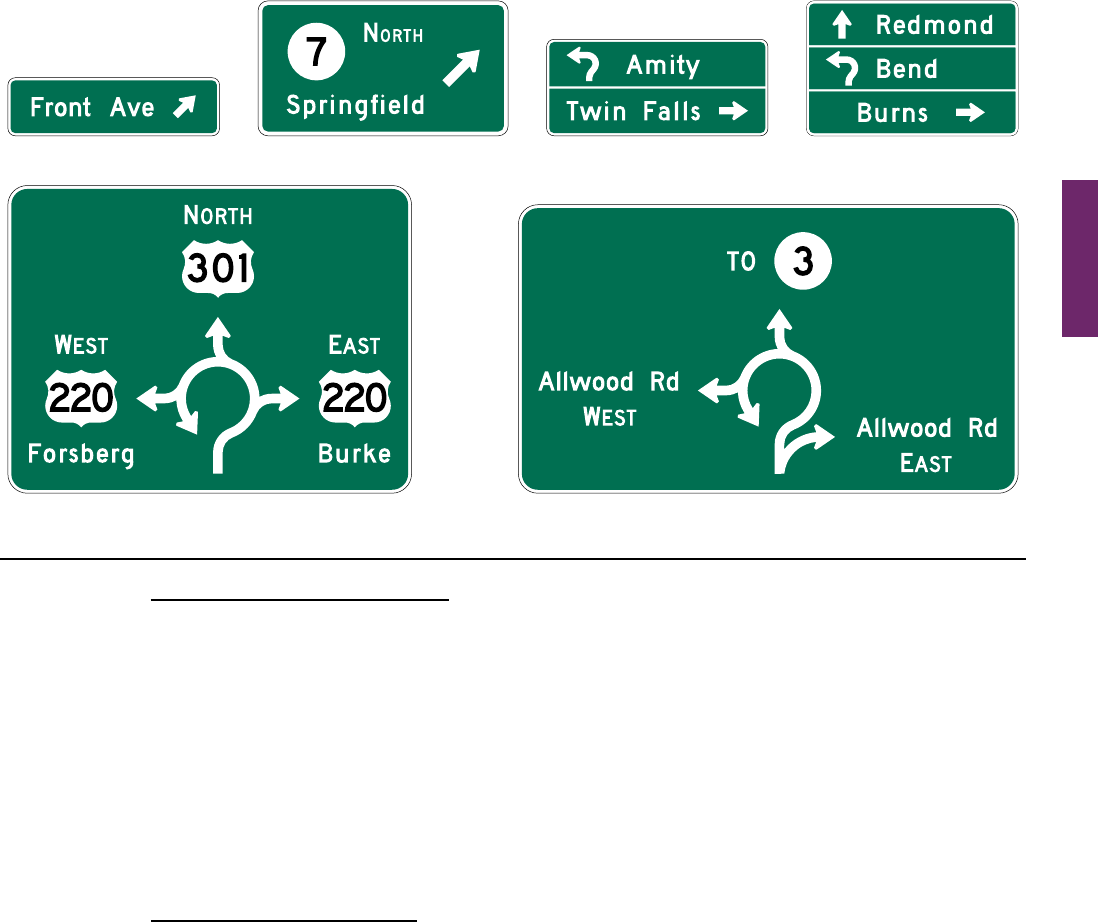
MUTCD 11th Edition Page 239
Month 2023December 2023
Sect. 2D.42 to 2D.43
Section 2D.42 Location of Destination Signs
Guidance:
01 When used in high-speed areas, Destination signs should be located 200 feet or more in advance of the
intersection, and following any Junction or Advance Route Turn assemblies that might be required. In rural areas,
the minimum distance between a Destination sign and either an Advance Route Turn assembly or a Junction
assembly should be 200 feet.
Option:
02 Inurbanareas,advancedistancesshorter thanthosespeciedinParagraph1ofthisSectionmaybeused.
03 BecausetheDestinationsignisoflesserimportancethantheJunction,AdvanceRouteTurn,orDirectional
assemblies,theDestinationsignmaybeeliminatedwhere the distance in which to provide adequate sign spacing
is limited.
Support:
04 Figure 2D-8showstypicalplacementsofDestinationsigns.
Section 2D.43 Distance Signs (D2 Series)
Standard:
01 If used, the Distance (D2-1 through D2-3) signs (see Figure 2D-9) shall be a horizontal rectangle of a
size appropriate for the required legend, displaying the names of no more than three cities, towns, junctions,
or other trafc generators, and the distance (to the nearest mile) to those places.
02 The distance numerals shall be placed to the right of the destination names as shown in Figure 2D-9.
Guidance:
03 The distance displayed should be selected on a case-by-case basis by the jurisdiction that owns the road or by
statewide policy. A well-dened central area or central business district should be used where one exists. In other
cases, the layout of the community should be considered in relation to the highway being signed and the decision
based on where it appears that most drivers would feel that they are in the center of the community in question.
04 The top name on the Distance sign should be that of the next place on the route having a post ofce or
a railroad station, a route number or name of an intersected highway, or any other signicant geographical
identity. The bottom name on the sign should be that of the next major destination or control city. If three
destinations are displayed, the middle line should be used to indicate communities of general interest along
the route or important route junctions.
Option:
05 ThechoiceofnamesforthemiddlelinemaybevariedonsuccessiveDistancesignstogiveroadusers
additionalinformationconcerningcommunitiesservedbytheroute.
Figure 2D-11. Destination Signs for Circular Intersections
D1-5
D1-1d
D1-1e D1-3dD1-2d
D1-5a

Page 240 MUTCD 11th Edition
Month 2023December 2023
Sect. 2D.43
400 ft
MIN.
200 ft
MIN.
100 to
200 ft
200 ft
MIN.
200 ft
MIN.
U.S. ROUTE 60
STATE ROUTE 12
U.S. ROUTE 60
25 to 200 ft
OR
300 ft
±
STATE ROUTE 37
STATE ROUTES
12 & 37
OR
Figure 2D-12. Examples of Guide Signs for Circular Intersections (Sheet 1 of 4)
Notes:
1. The spacings shown on this figure
are for rural intersections. See
Sections 2D.29, 2D.30, 2D.31,
2D.32, 2D.33, 2D.42, and 2D.44 for
low-speed and/or urban conditions.
2. Signs shown for only one direction.
See Chapter 2B for regulatory
signs and Chapter 2C for warning
signs at circular intersections. See
Chapter 3D for details on markings.
Directional
assembly
(optional)
Directional
assembly
(optional)
Directional
assembly
(optional)
Directional
assembly
(optional)
Confirming
assembly
(optional)
Advance
route turn
assembly
Junction
assembly
D1-2
D2-2 (optional)
D1-2d

MUTCD 11th Edition Page 241
Month 2023December 2023
Sect. 2D.43
WATER ST.
WATER ST.
400 ft
MIN.
100 to
200 ft
200 ft
MIN.
200 ft
MIN.
25 to
200 ft
200 ft
MIN.
300 ft
±
COUNTY ROUTE 571
COUNTY ROUTE 571
Figure 2D-12. Examples of Guide Signs for Circular Intersections (Sheet 2 of 4)
Notes:
1. The spacings shown on this figure
are for rural intersections. See
Sections 2D.29, 2D.30, 2D.31,
2D.32, 2D.33, 2D.42, and 2D.44 for
low-speed and/or urban conditions.
2. Signs shown for only one direction.
See Chapter 2B for regulatory
signs and Chapter 2C for warning
signs at circular intersections. See
Chapter 3D for details on markings.
OR
Exit destination
sign (optional)
Exit destination
sign (optional)
D2-2
(optional)
D1-2
D3-2
(optional)
D1-2d
Confirming
assembly
(optional)
Directional
assembly
(optional)
Destination sign
(optional)
Directional
assembly
(optional)
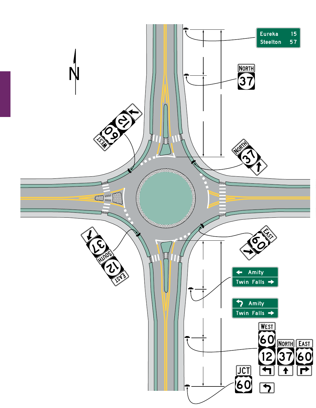
Page 242 MUTCD 11th Edition
Month 2023December 2023
Sect. 2D.43
U.S. ROUTE 60
STATE ROUTE 12
U.S. ROUTE 60
400 ft
MIN.
100 to
200 ft
200 ft
MIN.
200 ft
MIN.
25 to
200 ft
200 ft
MIN.
300 ft
±
Notes:
1. The spacings shown on this figure
are for rural intersections. See
Sections 2D.29, 2D.30, 2D.31,
2D.32, 2D.33, 2D.42, and 2D.44 for
low-speed and/or urban conditions.
2. Signs shown for only one direction.
See Chapter 2B for regulatory
signs and Chapter 2C for warning
signs at circular intersections. See
Chapter 3D for details on markings.
STATE ROUTE 37
Figure 2D-12. Examples of Guide Signs for Circular Intersections (Sheet 3 of 4)
OR
OR
STATE ROUTE
12 & 37
Confirming
assembly
(optional)
Directional
assembly
(optional)
Directional
assembly
(optional)
Directional
assembly
(optional)
Directional
assembly
(optional)
Advance
route turn
assembly
Junction
assembly
D1-2
D1-2d
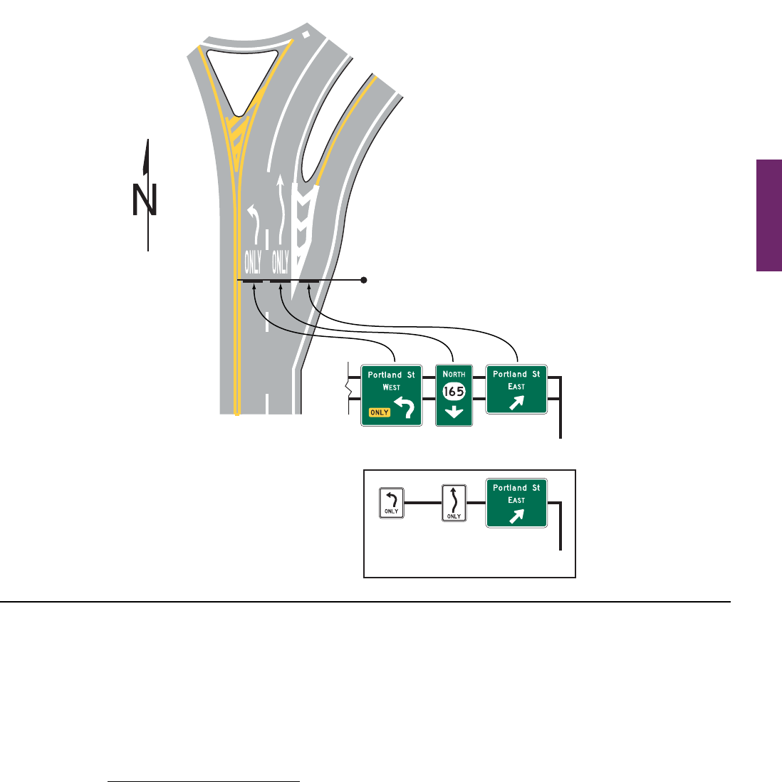
MUTCD 11th Edition Page 243
Month 2023December 2023
Guidance:
06 The control city should remain the same on all successive Distance signs throughout the length of the route
until that city is reached.
Option:
07 Ifmorethanonedistantpointmayproperlybedesignated,suchaswheretheroutedividesatsomedistance
aheadtoservetwodestinationsofsimilarimportance,andifthesetwodestinationscannotappearonthesame
sign,thetwonamesmaybealternatedonsuccessivesigns.
08 OnaroutecontinuingintoanotherState,destinationsintheadjacentStatemaybedisplayed.
Section 2D.44 Location of Distance Signs
Guidance:
01 If used, Distance signs should be installed on important routes leaving municipalities and just beyond
intersections of numbered routes in rural areas. If used, they should be placed just outside the municipal limits
or at the edge of the built-up area if it extends beyond the limits.
02 Where overlapping routes separate a short distance from the municipal limits, the Distance sign at the
municipal limits should be omitted. The Distance sign should be installed approximately 300 feet beyond the
separation of the two routes.
03 Where, just outside of an incorporated municipality, two routes are concurrent and continue concurrently to
the next incorporated municipality, the top name on the Distance sign should be that of the place where the routes
separate; the bottom name should be that of the city to which the greater part of the through trafc is destined.
Support:
04 Figures 2D-7 and 2D-8showtypicalplacementsofDistancesigns.
Alternate signing at overhead location
Overhead destination sign
with mandatory movement
lane control signs
R3-5
Series
R3-5
Series
Overhead destination signs
Note: Signs shown for only one direction.
See Chapter 2B for regulatory
signs and Chapter 2C for warning
signs at circular intersections. See
Chapter 3D for details on markings.
Figure 2D-12. Examples of Guide Signs for Circular Intersections (Sheet 4 of 4)
OR
Sect. 2D.43 to 2D.44

Page 244 MUTCD 11th Edition
Month 2023December 2023
Sect. 2D.44
Figure 2D-13. Examples of Signing for Intersections with Indirect Left Turns (Sheet 1 of 3)
A – Intercepted crossroad with left turns prohibited
OR
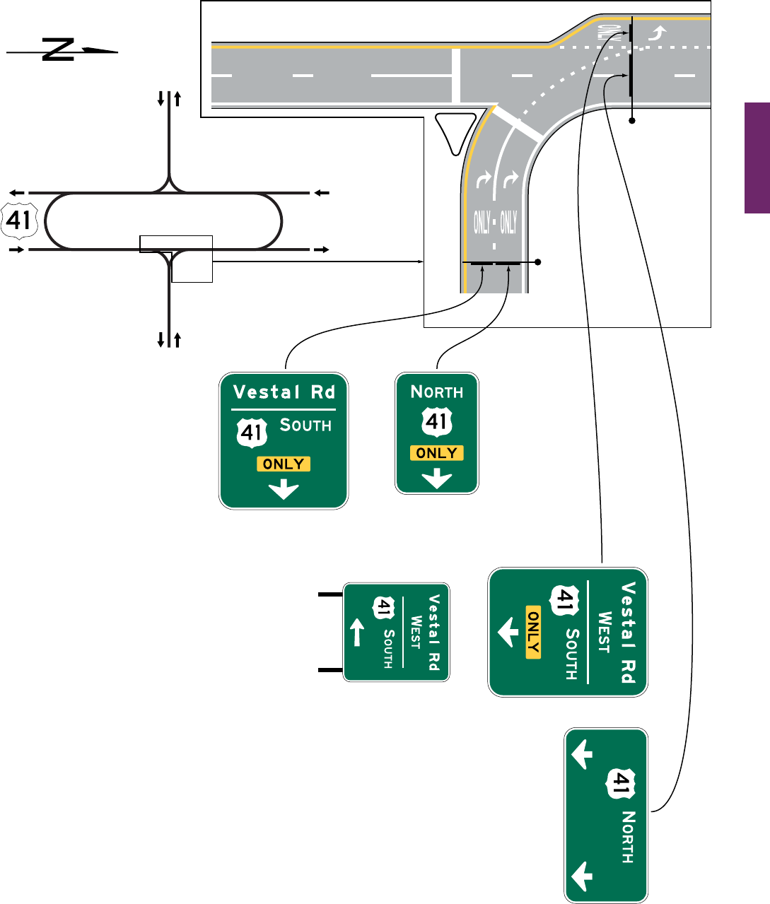
MUTCD 11th Edition Page 245
Month 2023December 2023
Sect. 2D.44
(post-mounted on left-hand
side of roadway)
Vestal Rd.
Vestal Rd.
Figure 2D-13. Examples of Signing for Intersections with Indirect Left Turns (Sheet 2 of 3)
B – Intercepted crossroad with left turns prohibited
OR
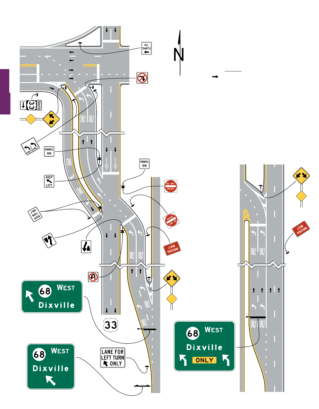
Page 246 MUTCD 11th Edition
Month 2023December 2023
Sect. 2D.44
Figure 2D-13. Examples of Signing for Intersections with Indirect Left Turns (Sheet 3 of 3)
C – Continuous flow intersection
OR
Location and layout when
overhead-mounted
Channelized left-
turn lanes
Non-channelized left-
turn lanes
Location and layout
when post-mounted
Legend
Direction of travel
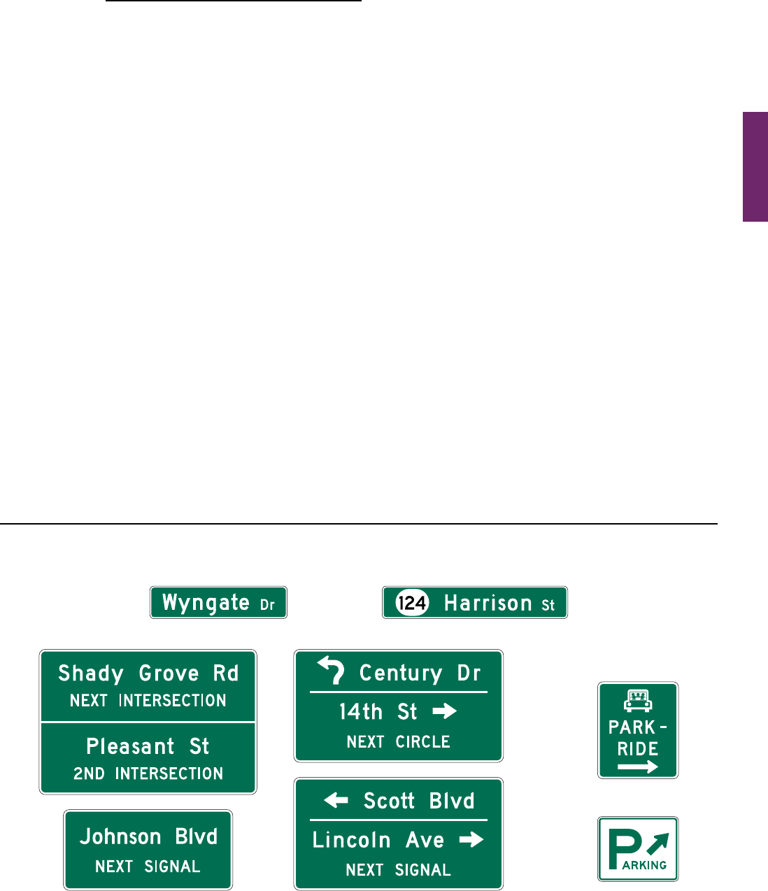
MUTCD 11th Edition Page 247
Month 2023December 2023
Sect. 2D.45
STREET NAME AND PARKING SIGNS
Section 2D.45 Street Name Signs (D3-1 and D3-1a)
Support:
01 StreetNamesignsatintersectionsandalongroadwaysprovideroaduserswithimportantnavigation
information.Section2H.10containsinformationaboutsignsusedtoidentifythenamesofgrade-separatedstreets,
railways, bikeways, or other transportation facilities.
Guidance:
02 Street Name (D3-1 or D3-1a) signs (see Figure 2D-14) should be installed in urban areas at all street
intersections regardless of other route signs that might be present and should be installed in rural areas to
identify important roads that are not otherwise signed.
03 To minimize wrong-way movements onto freeway or expressway exit ramps, Street Name signs should not
be used at the intersection of a freeway or expressway exit ramp with the crossroad to display the name of the
freeway or expressway to trafc on the crossroad.
Option:
04
ForstreetsthatarepartofaU.S.,State,orcountynumberedroute,aD3-1aStreetNamesign(seeFigure 2D-14)
thatincorporatesarouteshieldmaybeusedtoassistroaduserswhomightnototherwisebeabletoassociatethe
nameofthestreetwiththeroutenumber.
Standard:
05 The lettering for names of streets and highways on Street Name signs shall be composed of a
combination of lower-case letters with initial upper-case letters (see Section 2A.08).
Guidance:
06 The determination of letter heights to be used on Street Name signs should be based on, but not limited to, the
following considerations:
A. Use of Advance Street Name signs (see Section 2D.46);
B. Number of lanes on the intersection approach;
C. Length of turn lanes;
D. Distance the Street Name sign is located across the intersection (if a sign is not provided on the near side
of the intersection).
07 Letter heights on street name signs should be as shown in Table 2D-6.
Figure 2D-14. Street Name and Parking Signs
D3-1
D3-1a
D4-1
D4-2
D3-2
OR

Page 248 MUTCD 11th Edition
Month 2023December 2023
Sect. 2D.45
Option:
08 Fortwo-lanelocalroadwayswithspeedlimitsof25mphorless,theletteringonpost-mountedStreetName
signsmaybecomposedofinitialupper-caselettersatleast4inchesinheightandlower-caselettersatleast3
inches in nominalloop height.
Support:
09 TherecommendedminimumletterheightsforStreetNamesignsaresummarizedinTable2D-6.Thespeed
limitsspeciedandtherecommendedminimumletterheightsprovidedinthisSectionapplytotheroadwaythat
eachStreetNamesignfacesratherthantothestreetthathasitsnamedisplayedontheStreetNamesign.Theletter
heightsspeciedinTable2D-6aretheinitialupper-caseletterofamixed-caselegend.
10 Aminimumupper-case letter height of 12 inches withalower-casenominalloopheightof9inchesis
recommendedforalloverheadStreetNamesignsregardlessofpostedspeedlimitasStreetNamesignsgenerally
require greater legibility distances for road users to properly react.
Option:
11 EachStreetNamesigninasignassemblymayusedifferentletterheightsdeterminedbythespeedlimitofthe
street that each sign faces.
12 Theletterheightofthestreetnamedescriptor(suchasSt,Ave,orRd),thedirectionallegend(suchasNW),or
anyothersupplementallegend(suchasblockorhousenumbers)ontheD3-1andD3-1asignsmaybesmallerthan
thatofthestreetnameitself.
Guidance:
13 The letter height of the street name descriptor, the directional legend, or any other supplemental legend on
the D3-1 and D3-1a signs should be at least two-thirds of the letter height of the street name itself, but not less
than 3 inches for the initial upper-case letters and not less than 2.25 inches for the nominal loop height of the
lower-case letters.
14 Conventional abbreviations (see Section 1D.08) should be used except for the street name itself. Acceptable
abbreviations for street name descriptors such as “Ave” for Avenue and “Blvd” for Boulevard should be as
provided in Table 2D-3 (see Section 2D.07). The street name descriptors that are provided in Table 2D-4 should
not be abbreviated (see Section 2D.07).
Option:
15 BlockorhousenumbersmaybedisplayedasasupplementallegendonaStreetNamesigntoaidemergency
responders and road users in locating addresses.
Guidance:
16 If block or house numbers are displayed on a Street Name sign where only a single Street Name sign is
provided for the crossroad, the block or house numbers for the left and right blocks should be positioned at the
left and right sides of the sign, respectively.
17 If block or house numbers are displayed on a Street Name sign where two Street Name signs are provided for
the crossroad, such as on diagonally opposite corners of an intersection, each Street Name sign should display
only the block or house numbers associated with that block of the crossroad.
Option:
18 Apictograph(seedenitioninSection1C.02)representingthemunicipality,inaccordancewiththeprovisions
ofSection2A.04,maybeusedonaD3-1sign.Forstreetnetworksundertheprimaryjurisdictionofanother
governmental-approvedentity,suchaswithinacollegeoruniversitycampus,withinamilitarybase,orwithina
transportation facility (such as an airport or port), a pictograph representing that entity, in accordance with the
provisionsofSection2A.04,maybeusedonaD3-1signwithinthejurisdictionalboundariesofthat entit y.
Table 2D-6. Minimum Letter Heights on Street Name Signs
Type of
Mounting
Type of Street or
Highway
Speed Limit
Recommended Minimum
Letter Height *
Initial Upper-Case Lower-Case
Overhead All types All speed limits 12 inches 9 inches
Post-mounted Multi-lane More than 40 mph 8 inches 6 inches
Post-mounted Multi-lane 40 mph or less 6 inches 4.5 inches
Post-mounted 2-lane All speed limits 6 inches** 4.5 inches**
* Letter heights shown are for the street name. Descriptors or other supplementary legend may be displayed in smaller lettering of at least 3 inches.
** On two-lane local streets with speed limits of 25 mph or less, 4-inch initial upper-case letters with 3-inch lower-case letters may be used.

MUTCD 11th Edition Page 249
Month 2023December 2023
Standard:
19 Pictographs shall not be displayed on D3-1a or Advance Street Name (D3-2) signs (see Section 2D.46).
20 If a pictograph is used on a D3-1 sign, the height and width of the pictograph shall not exceed the upper-
case letter height of the principal legend of the sign.
Guidance:
21 The pictograph should be positioned to the left of the street name.
22 Pictographs should not be used on a D3-1 sign that contains directional arrows.
Standard:
23
The Street Name sign shall be retroreective or illuminated in accordance with the provisions of
Section 2A.21.
Option:
24 Thebordermaybeomittedfromapost-mountedStreetNamesign.
Guidance:
25 The decision to omit the border from a post-mounted Street Name sign should be based on such factors as the
visual complexity of the environment and the degree of conspicuity needed to provide for adequate recognition of
the sign by the road user.
Option:
26 An alternative background color (see Paragraph 28 of this Section) other than the standard guide sign color of
greenmaybeusedforStreetName(D3-1orD3-1a)signswherethehighwayagencydeterminesthisisnecessary
toassistroadusersindeterminingjurisdictionalauthorityforroads.
Standard:
27
Alternative background colors shall not be used for Advance Street Name (D3-2) signs (see Section 2D.46).
28 The only acceptable alternative background colors for Street Name (D3-1 or D3-1a) signs shall be blue,
brown, or white. Regardless of whether green, blue, or brown is used as the background color for Street
Name (D3-1 or D3-1a) signs, the legend (and border, if used) shall be white. For Street Name signs that use
a white background, the legend (and border, if used) shall be black.
Guidance:
29 An alternative background color for Street Name signs, if used, should be applied to the Street Name (D3-1
or D3-1a) signs on all roadways under the jurisdiction of a particular highway agency.
30 In business or commercial areas and on principal arterials, Street Name signs should be placed at least
on diagonally opposite corners. In residential areas, at least one Street Name sign should be mounted at each
intersection. Signs naming both streets should be installed at each intersection. They should be mounted with
their faces parallel to the streets they name.
31 Where used, Street Name signs should display their legends on both the front and back sides of the sign to
facilitate navigation for pedestrians.
Option:
32 Tooptimizevisibility,StreetNamesignsmaybemountedoverhead.StreetNamesignsmayalsobeplaced
abovearegulatoryorSTOPorYIELDsignwithnorequiredverticalseparation.
Guidance:
33 In urban or suburban areas, especially where Advance Street Name signs for signalized and other major
intersections are not used, the use of overhead Street Name signs should be strongly considered.
Option:
34 Atintersectioncrossroadswherethesameroadhastwodifferentstreetnamesforeachdirectionoftravel,both
streetnamesmaybedisplayedonthesameStreetName(D3-1)signalongwithTypeDdirectionalarrows,except
whereonearrowwouldpointinadirectionopposingtheowoftrafconaone-waystreetorwhereaturninthe
direction of the arrow is not allowed.
35 Onlower-speedroadways,historicstreetnamesignswithinlocallyidentiedhistoricdistrictsthatare
consistentwiththecriteriacontainedin36CFR60.4forsuchstructuresanddistrictsmayremaininservice
withoutcomplyingwiththeprovisionsofParagraphs3,4,6,9,12through14,and18through20ofthisSection.
Guidance:
36 Streets or segments of a street that have been memorialized or dedicated should not use a second Street Name
sign to display the memorial or dedication name (see Section 2D.56). When signed, the Memorial or Dedication
sign should be located to minimize its conspicuity to and potential for confusion.
Sect. 2D.45

Page 250 MUTCD 11th Edition
Month 2023December 2023
Sect. 2D.46
Support:
37 Informationregardingtheuseofstreetnamesonsupplementalplaquesforusewithintersection-related
warning signs is contained in Section 2C.65.
38 Informationregardingtheidenticationofovercrossingandundercrossingroadwaysatgradeseparationsis
containedinSection2H.10.
Section 2D.46 Advance Street Name Signs (D3-2 Series)
Support:
01 AdvanceStreetName(D3-2)signs(seeFigure 2D-14)identifyadownstreamintersection.Althoughthis
is often the next intersection, it could also be several intersections away in cases where the next signalized
intersection is referenced.
Standard:
02 Advance Street Name (D3-2) signs, if used, shall supplement rather than be used instead of the Street
Name (D3-1 or D3-1a) signs at the intersection.
Option:
03 AdvanceStreetName(D3-2)signsmaybeinstalledinadvanceofsignalizedorunsignalizedintersectionsto
provideroaduserswithadvanceinformationtoidentifythename(s)ofthenextintersectingstreettopreparefor
crossingtrafcandtofacilitatetimelydecelerationand/orlanechanginginpreparationforaturn.
Guidance:
04 On arterial highways in rural areas, Advance Street Name signs should be used in advance of all signalized
intersections and in advance of all intersections with mandatory turn lanes.
05 In urban areas, Advance Street Name signs should be used in advance of all signalized intersections on major
arterial streets, except where signalized intersections are so closely spaced that advance placement of the signs is
impracticable.
06 The heights of the letters on Advance Street Name signs should comply with the provisions of Section 2D.05.
Standard:
07 If used, Advance Street Name signs shall have a white legend and border on a green background.
Alternative background colors shall not be used on Advance Street Name signs.
08 If used, Advance Street Name signs shall provide the name(s) of the intersecting street(s) on the top
line(s) of the legend and the distance to the intersecting streets or messages such as NEXT SIGNAL, NEXT
INTERSECTION, NEXT CIRCLE, or directional arrow(s) on the bottom line of the legend.
09 Pictographs shall not be displayed on Advance Street Name signs.
Option:
10 Directionalarrow(s)maybeplacedtotherightorleftofthestreetnameormessagesuchasNEXTSIGNAL,
asappropriate,ratherthanonthebottomlineofthelegend.Curved-stemarrowsmaybeusedonAdvanceStreet
Namesignsonapproachestocircularintersections.
11 Forintersectingcrossroadswherethesameroadhasadifferentstreetnameforeachdirectionoftravel,the
differentstreetnamesmaybedisplayedonthesameAdvanceStreetNamesignalongwithdirectionalarrows.
12 Inadvanceoftwoclosely-spacedintersectionswhereitisimpracticabletoinstallseparateAdvanceStreet
Namesigns,theAdvanceStreetNamesignmayincludethestreetnamesforbothintersectionsalongwith
appropriatesupplementallegendsforbothstreetnames,suchasNEXTINTERSECTION,2NDINTERSECTION,
orNEXTLEFTandNEXTRIGHT,ordirectionalarrows.
Guidance:
13 If two street names are used on the Advance Street Name sign, the street names should be displayed in the
following order:
A. For a single intersection where the same road has a different street name for each direction of travel, the
name of the street to the left should be displayed above the name of the street to the right; or
B. For two closely-spaced intersections, the name of the rst street encountered should be displayed above
the name of the second street encountered, and the arrow associated with the second street encountered
should be an advance arrow, such as the arrow shown on the W16-6P arrow plaque (see Figure 2C-16).
Option:
14 AnAdvanceStreetName(W16-8PorW16-8aP)plaque(seeSection2C.65)withblacklegendonayellow
background,installedtosupplementanIntersection(W2series)orAdvanceTrafcControl(W3series)warning
signmaybeusedinsteadofanAdvanceStreetNameguidesign.

MUTCD 11th Edition Page 251
Month 2023December 2023
Sect. 2D.47 to 2D.48
Section 2D.47 Parking Area Guide Sign (D4-1)
Option:
01 The Parking Area (D4-1) guide sign (see Figure 2D-14)maybeusedtoshowthedirectiontoanearbypublic
parking area or parking facility.
Standard:
02 The smaller size of 18 x 15 inches for the Parking Area guide sign shall be limited to minor, low-
speed streets.
Guidance:
03 If used, the Parking Area guide sign should be installed on major thoroughfares at the nearest point of access
to the parking facility and where it can advise drivers of a place to park. The sign should not be used more than
four blocks from the parking area.
Section 2D.48 PARK - RIDE Sign (D4-2)
Option:
01 APARK-RIDE(D4-2)sign(seeFigure 2D-14)maybeusedtodirectroaduserstopark-and-ridefacilities.
Standard:
02
The signs shall display the word message PARK - RIDE and direction information (arrow or
word message).
Option:
03 PARK-RIDEsignsmaydisplaythelocaltransitpictographand/orcarpoolsymbol.
Standard:
04 If used, the local transit pictograph and/or carpool symbol shall be located in the top part of the sign
above the message PARK - RIDE. In no case shall the vertical dimension of the local transit pictograph
and/or carpool symbol exceed 18 inches.
Guidance:
05 If the function of the parking facility is to provide parking for persons using public transportation, the local
transit pictograph should be used on the guide sign. If the function of the parking facility is to serve carpool
riders, the carpool symbol should be used on the guide sign. If the parking facility serves both functions, both
the pictograph and carpool symbol should be used.
Standard:
06 These signs shall have a white legend and border on a rectangular green background. The carpool
symbol shall be as shown for the D4-2 sign. The color of the local transit pictograph shall be selected by
the local transit authority.
Option:
07 To increase the target value and contrast of the local transit pictograph, and to allow the local transit
pictographtoretainitsdistinctivecolorandshape,thepictographmaybeincludedwithinawhiteborderor
placed on a white background.

Page 252 MUTCD 11th Edition
Month 2023December 2023
Sect. 2D.49
FREEWAY INTERCHANGE APPROACH SIGNS
Section 2D.49 Signing on Conventional Roads on Approaches to Interchanges
Support:
01 Becausethereareanumberofdifferentrampcongurationsthatarecommonlyusedatinterchangeswith
conventional roads, drivers on the conventional road cannot reliably predict whether they will be required to turn
leftorrightinordertoenterthecorrectramptoaccessthefreewayorexpresswayinthedesireddirectionof
travel. Consistently applied signing for conventional road approaches to freeway or expressway interchanges is
highly desirable.
Standard:
02 On multi-lane conventional roads approaching an interchange, guide signs shall be provided to identify
which direction of turn is to be made and/or which specic lane to use for ramp access to each direction of
the freeway or expressway.
Guidance:
03 The signing of conventional roads with one lane of trafc approaching an interchange should consist of a
sequence containing the following signs (see Figure 2D-15):
A. Junction Assembly
B. Destination sign
C. Directional Assembly or Entrance Direction sign for the rst ramp
D. Advance Route Turn Assembly or Advance Entrance Direction sign with an advance turn arrow
E. Directional Assembly or Entrance Direction sign for the second ramp
Standard:
04 If used, the Entrance Direction sign shall consist of a white legend and border on a green background.
It shall contain the freeway or expressway route shield(s), cardinal direction, and directional arrow(s).
Option:
05 TheEntranceDirectionsignmaycontainadestination(s)and/oranactionmessagesuchasNEXTRIGHT.
06 Atminorinterchanges(seeSection2E.30),thefollowingsequenceofsignsmaybeused(seeFigure 2D-16):
A. JunctionAssembly
B. DirectionalAssemblyfortherstramp
C. DirectionalAssemblyforthesecondramp
Guidance:
07 On multi-lane conventional roads approaching an interchange, the sign sequence should contain the
following signs (see Figures 2D-17 through 2D-19):
A. Junction Assembly
B. Advance Entrance Direction sign(s) for both directions (if applicable) of travel on the freeway
or expressway
C. Entrance Direction sign for rst ramp
D. Advance Turn Assembly
E. Entrance Direction sign for the second ramp
Support:
08 Advance Entrance Direction signs are used to direct road users to the appropriate lane(s).
Standard:
09 The Advance Entrance Direction sign shall consist of a white legend and border on a green background.
It shall contain the freeway or expressway route shield(s) and cardinal direction(s).
Option:
10 TheAdvanceEntranceDirectionsignmayhavedestinations,directionalarrows,and/oranactionmessage
suchasKEEPLEFT,NEXTLEFT,orSECONDRIGHT.Signsinthissequencemaybemountedoverheadto
improvevisibilityasshowninFigures 2D-17 through 2D-19.
Support:
11 Apost-mountedAdvanceEntranceDirectiondiagrammaticsign(seeFigure 2D-20), within the sequence
ofapproachguidesigningdescribedinParagraphs3,6,and7ofthisSection,mightbehelpfulindepictingthe
locationofafreewayorexpresswayentrancerampthatisincloseproximitytoaninterveningintersectiononthe
samesideoftheapproachroadwayandwheresigningforonlytherampmightcauseconfusiontoroadusers.
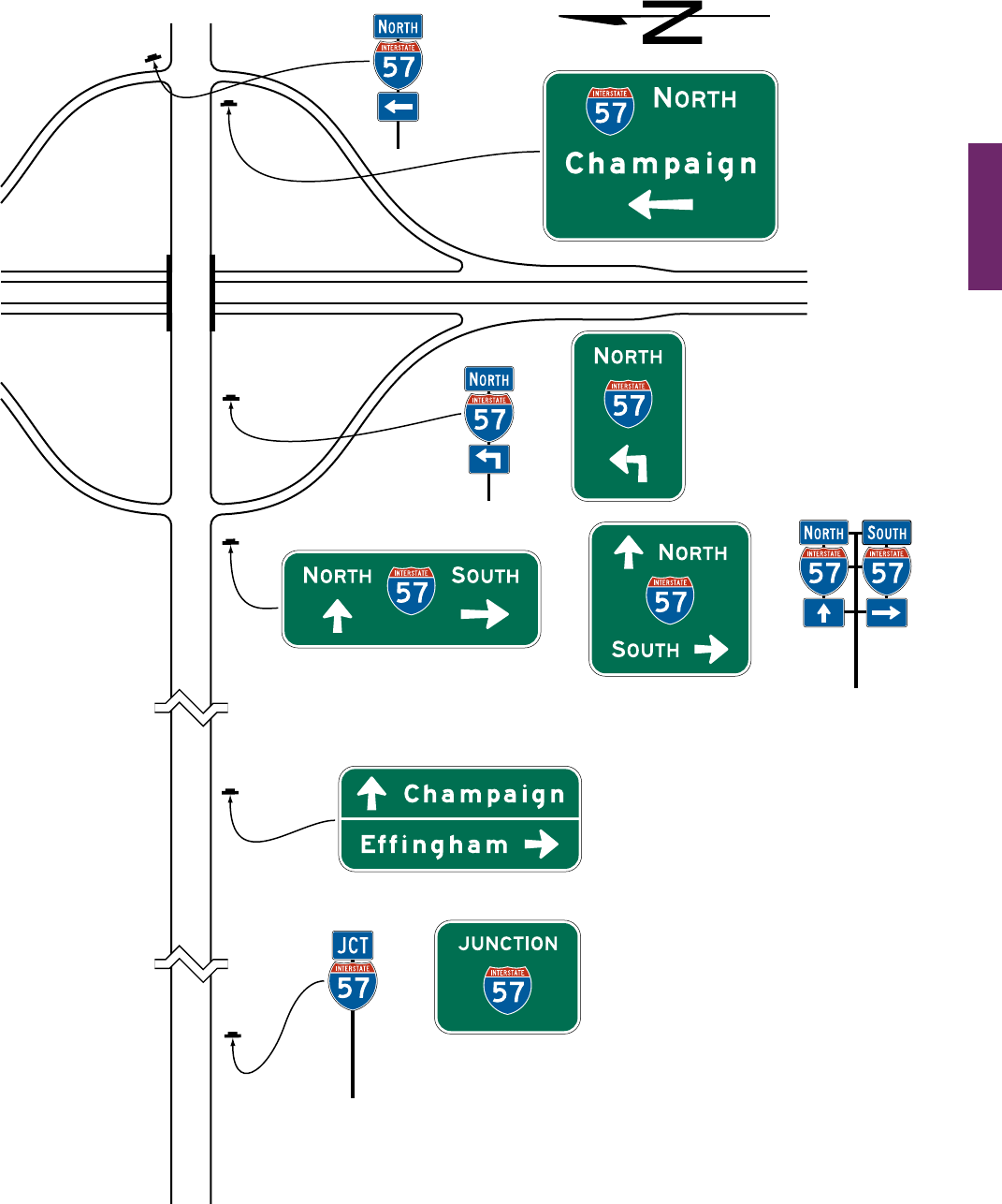
MUTCD 11th Edition Page 253
Month 2023December 2023
Sect. 2D.49
Figure 2D-15. Example of Interchange Crossroad Guide Signing
for a One-Lane Approach
OR
OR
(optional)
OR
I-57
OR
Notes:
1. Signs shown for only one direction of travel.
2. See Chapter 2B for regulatory signs and
Chapter 2C for warning signs.
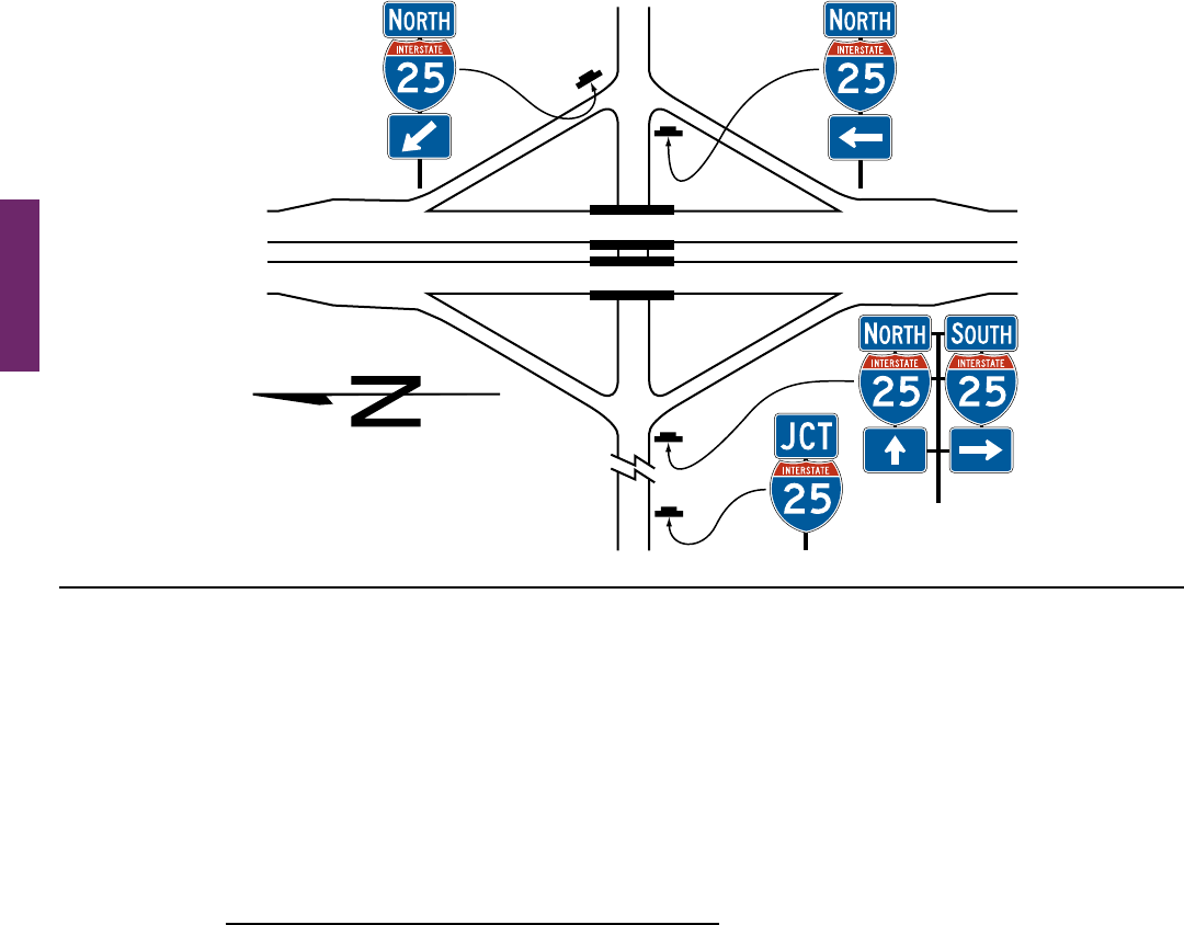
Page 254 MUTCD 11th Edition
Month 2023December 2023
Standard:
12 If used, the post-mounted Advance Entrance Direction diagrammatic sign shall display only the two
successive turns from the same side of the roadway, one of which shall be the entrance ramp. The post-
mounted Advance Entrance Direction sign shall depict only the successive turns and shall not depict lane
use with lane lines, multiple arrow shafts for the approach roadway, action messages, or other representations.
Support:
13
Exampleguidesigningforatransposed-alignmentcrossroadatadiamondinterchangeisshowninFigure 2D-21.
Exampleguidesigningfor a single-point urban intersection atadiamondinterchangeis shown in Figure 2D-22.
14 Section2D.50containsinformationregardingtheuseofaDirectionalassemblyoraFREEWAYENTRANCE
signtomarktheentrancetoafreewayorexpresswayatthefarcornerofanintersection.
Section 2D.50 Freeway Entrance Signs (D13-3 and D13-3a)
Option:
01 FREEWAY ENTRANCE (D13-3) signs or FREEWAY ENTRANCE with diagonal downward-pointing arrow
(D13-3a) signs (see Figure 2D-18)maybeusedonentrancerampsnearthecrossroadtoinformroadusersofthe
freeway or expressway entrance, as appropriate.
02 TheD13-3andD13-3asignsmaydisplayanalternatelegendinplaceofFREEWAY,suchasEXPRESSWAY
orPARKWAY,asappropriate,ormaydisplaythenameofanunnumberedhighway.
03 ADirectionalassembly(seeSection2D.32)withadiagonaldownward-pointingarrow(M6-2aP)auxiliary
plaque(seeSection2D.28)maybeusedatthefarleft-handcornerofanintersectionwithafreewayorexpressway
entrancerampasanalternativetotheD13-3asign,facingleft-turningtrafcontheconventionalroadapproach
toindicatetheimmediatepointofentrytothefreewayorexpresswayanddistinguishtheentrancerampfroman
adjoiningexitrampterminalatthesameintersectionwiththeconventionalroad(seeFigure 2D-18).Asimilar
Directionalassemblymaybeusedatthefarright-handcornerofanintersectionwithafreewayorexpressway
entrancerampwheretheentrancerampandacrossroadorsideroadfollowoneanotherinclosesuccessiononthe
conventionalroadapproachandthepointofentrytothefreewayorexpresswaymightbedifcultfortheroaduser
todistinguishfromthecrossroadorsideroadontheconventionalroadapproach(seeFigure 2D-20).
Support:
04 Section2B.48containsinformationregardingtheuseofregulatorysignstodeterwrong-waymovementsat
intersectionsoffreewayorexpresswayrampswithconventionalroads,andintheareawhereentranceramps
intersectwiththemainlinelanes.
Figure 2D-16. Example of Minor Interchange Crossroad Guide Signing
I-25
(optional)
Notes:
1. Signs shown for only one direction of travel.
2. See Chapter 2B for regulatory signs and
Chapter 2C for warning signs.
Sect. 2D.49 to 2D.50
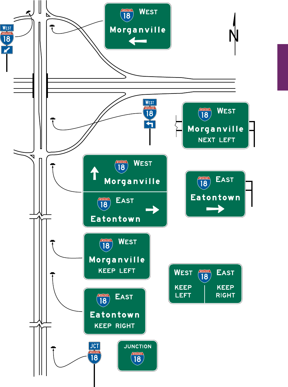
MUTCD 11th Edition Page 255
Month 2023December 2023
Sect. 2D.50
Figure 2D-17. Examples of Multi-Lane Crossroad Guide Signing
for a Diamond Interchange
OR
I-18
OR
OR
OR
(mounted overhead)
(mounted overhead)
Notes:
1. Signs shown for only one
direction of travel.
2. See Chapter 2B for regulatory
signs and Chapter 2C for
warning signs.
(optional)

Page 256 MUTCD 11th Edition
Month 2023December 2023
Figure 2D-18. Examples of Multi-Lane Crossroad Guide Signing
for a Partial Cloverleaf Interchange
OR
I-13
OR
OR
Directional
Assembly
(optional)
OR
OR
(mounted overhead)
OR OR
D13-3
(optional)
D13-3a
(optional)
Directional
assembly
(optional)
Notes:
1. Signs shown for only
one direction of travel.
2. See Chapter 2B for
regulatory signs and
Chapter 2C for warning
signs.
3. See Section 2B.48 and
Figure 2B-15 for an
example of regulatory
signing and pavement
markings at an exit
ramp termination to
deter wrong-way entry.
D13-3
(optional)
D13-3a
(optional)
Sect. 2D.50
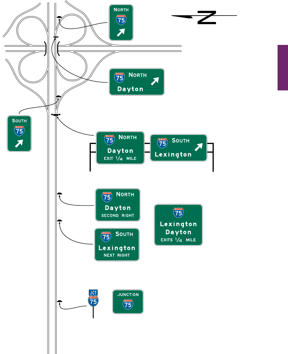
MUTCD 11th Edition Page 257
Month 2023December 2023
Sect. 2D.50
Locate on or in front of bridge
if freeway goes over crossroad
OR
OR
I-75
Figure 2D-19. Examples of Multi-Lane Crossroad Signing
for a Cloverleaf Interchange
(mounted overhead)
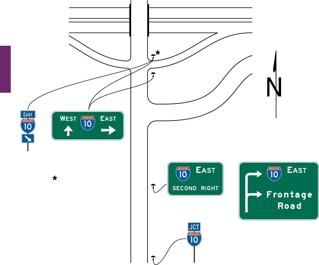
Page 258 MUTCD 11th Edition
Month 2023December 2023
Sect. 2D.50
Figure 2D-20. Example of Crossroad Guide Signing for an Entrance Ramp
with a Nearby Frontage Road
Frontage Road
OR
See Figures 2D-15 through
2D-19 for additional signing
on crossroad approaches
Location for directional
assembly or alternate location
for guide sign depending on
distance between ramp and
frontage road intersections
I-10
OR
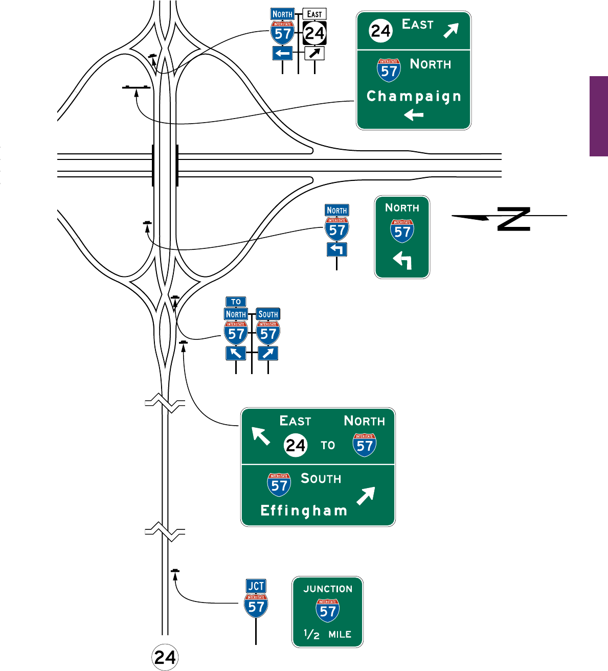
MUTCD 11th Edition Page 259
Month 2023December 2023
Sect. 2D.50
Figure 2D-21. Example of Transposed Alignment Crossroad Guide Signing
at a Diamond Interchange
OR
I-57
OR
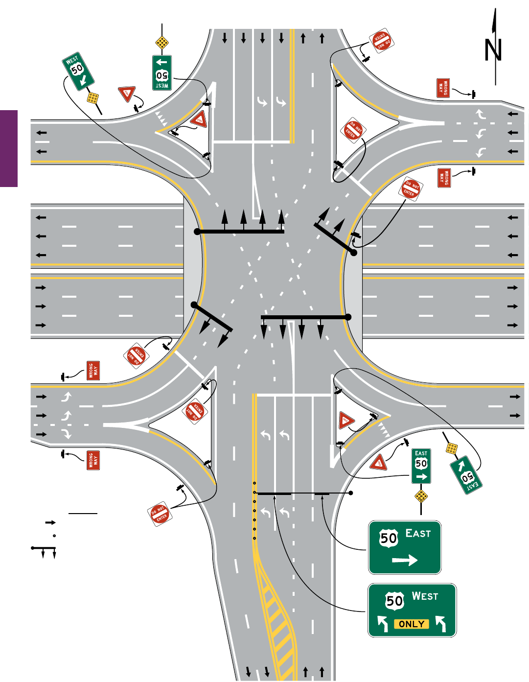
Page 260 MUTCD 11th Edition
Month 2023December 2023
Sect. 2D.50
US 50
Figure 2D-22. Example of Crossroad Intersection Guide Signs
for a Single-Point Urban Interchange
Legend
Direction of travel
Tubular marker
Signal mast arm/signal heads
Notes:
1. See Figures 2D-16 and 2D-17 for
examples of approach guide signing.
2. Some regulatory signs and traffic signals
are shown for reference only.

MUTCD 11th Edition Page 261
Month 2023December 2023
Sect. 2D.51 to 2D.52
WEIGH STATION, CROSSOVER, TRUCK AND PASSING LANE,
AND EMERGENCY AND SLOW VEHICLE TURN-OUT SIGNS
Section 2D.51 WEIGH STATION Signing (D8 Series)
Support:
01 Independentfacilitiesorareashavebeenaddedalongmanyhighwayswherecertaincommercialvehiclesare
directedtostoptobeweighedand/orinspected.Theseareasaresometimespermanent,suchasinaroadsidearea,
ortemporarymobilefacilitiesdeployedalongtheroadway.
02 ThegeneralconceptforsigningpermanentWeighStationsissimilartosigningRestAreas(seeSection2I.05)
becauseinbothcasestrafcusingeitherarearemainswithintheright-of-way.
Standard:
03 The standard sequence of signs for a Weigh Station on a conventional highway shall include three basic
signs (see Figure 2D-23):
A. Weigh Station Advance (D8-1) sign,
B. Weigh Station Advance Direction (D8-2) sign, and
C. Weigh Station Entrance Direction (D8-3) sign.
Guidance:
04 A Gore sign with the same basic legend as the Weigh Station Entrance Direction (D8-3) sign should also be
used to emphasize the entrance to the weigh station.
Option:
05 Where State law requires trucks of a certain weight to enter the Weigh Station, a Weigh Station (R13-1)
regulatorysign(seeSection2B.65)maybelocatedfollowingtheAdvanceWeighStationAheadsign
(see Figure 2D-23).
06 Whereonlycommercialvehicleinspectionsareconductedintheinspectionarea,theWEIGHSTATION
legendoftheD8seriessignsmaybereplacedwiththealternatelegend,COMMERCIALVEHICLE
INSPECTION.
Guidance:
07 The Weigh Station Advance Direction (D8-2) Sign or the Weigh Station Advance (D8-1) sign should display,
either on the sign or on a supplemental plaque or sign panel, the changeable legend OPEN or CLOSED.
Standard:
08 When the WEIGH STATION legend of the D8 series signs is replaced with the COMMERCIAL
VEHICLE INSPECTION legend, as provided in Paragraph 6 of this Section, the WEIGH STATION legend
of the R13-1 sign shall likewise be replaced with the alternate legend.
Section 2D.52 Crossover Signs (D13-1 and D13-2)
Option:
01 Crossoversignsmaybeinstalledondividedhighwaystoidentifymedianopeningsnototherwiseidentiedby
warning or other guide signs.
Standard:
02 A Crossover (D13-1) sign (see Figure 2D-24) shall not be used to identify a median opening that is
permitted to be used only by ofcial or authorized vehicles.
Guidance:
03 If used, the Crossover sign should be installed immediately beyond the median opening, either on the right-
hand side of the roadway or in the median.
Option:
04 The Advance Crossover (D13-2) sign (see Figure 2D-24)maybeinstalledinadvanceoftheCrossoversignto
provide advance notice of the crossover.
Guidance:
05 The distance displayed on the Advance Crossover sign should be 1 MILE, ½ MILE, or ¼ MILE, unless
unusual conditions require some other distance. If used, the sign should be installed either on the right-hand side
of the roadway or in the median at approximately the distance displayed on the sign.
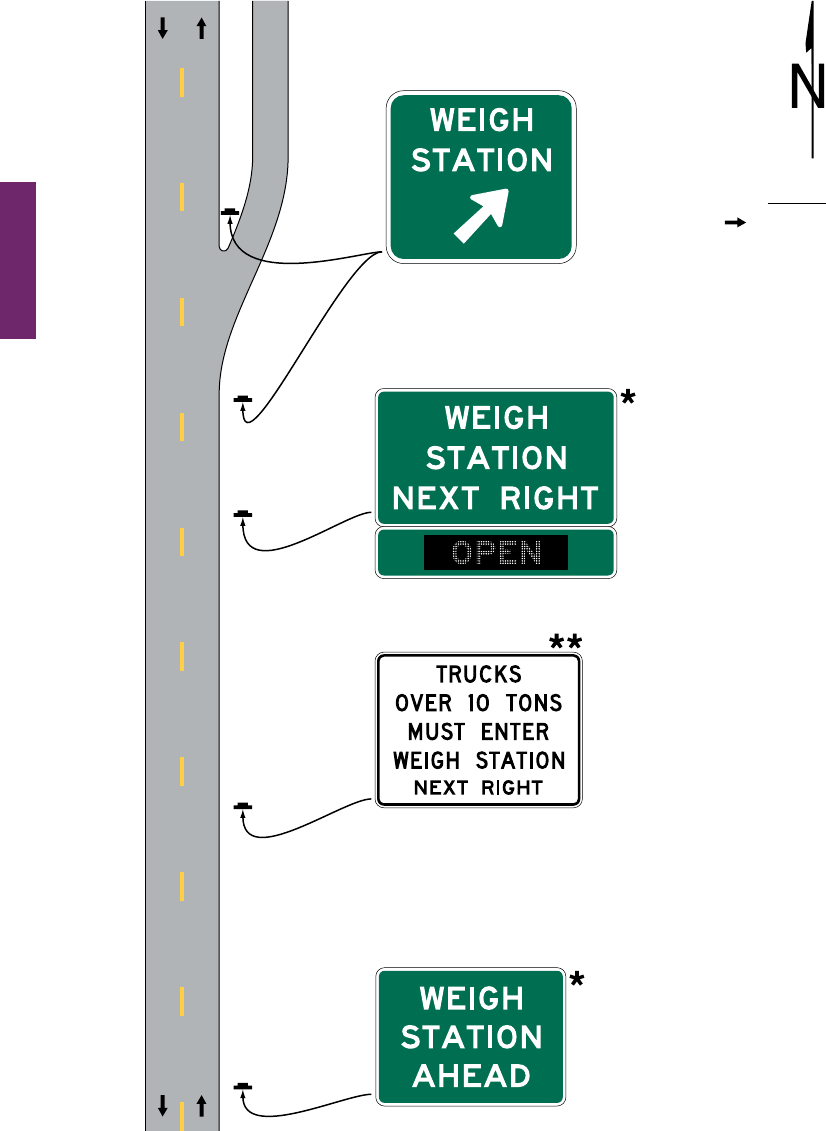
Page 262 MUTCD 11th Edition
Month 2023December 2023
Sect. 2D.52
Figure 2D-23. Example of Weigh Station Signing – Conventional Road
Legend
Direction of travel
D8-1a
D8-2
R13-1
D8-3
The D8-1a or the D8-2 sign
should display, either within the
sign border or on a supplemental
sign panel, the changeable
message OPEN or CLOSED.
An R13-1 sign (see Section 2B.65)
should be used only where State law
requires trucks of a certain weight to
enter the weigh station.
6 in
*
**
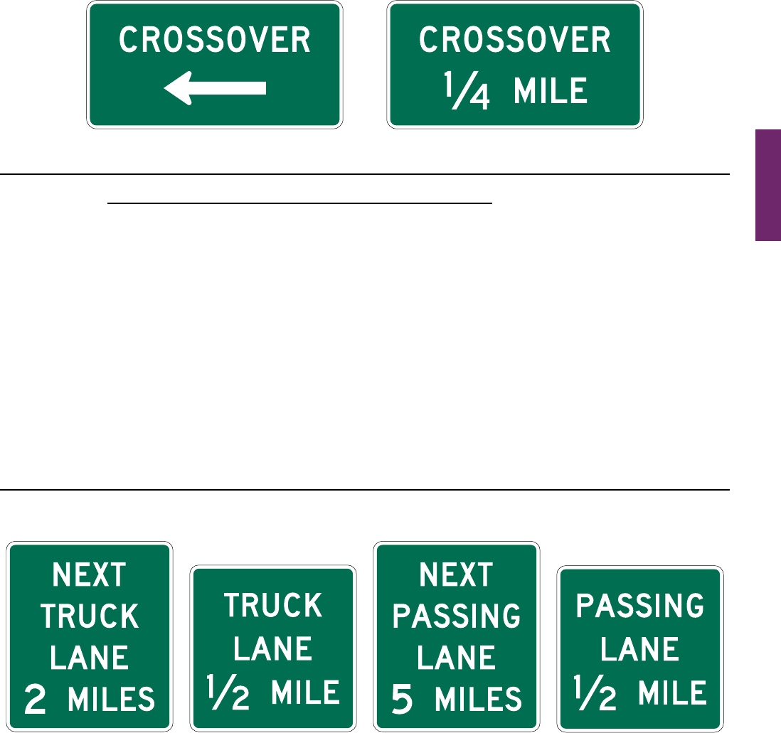
MUTCD 11th Edition Page 263
Month 2023December 2023
Sect. 2D.53
Section 2D.53 Truck and Passing Lane Signs (D17-1 through D17-4)
Guidance:
01 If an extra lane has been provided to the right-hand side of the travel lane for use by trucks and other slow-
moving trafc, an Advance Truck Lane (D17-2) sign (see Figure 2D-25) should be installed in advance of the lane.
02 If a series of truck lanes is provided along a highway, a Next Truck Lane (D17-1) sign (see Figure 2D-25)
should be installed after each truck lane segment.
03 If an extra lane has been provided to the left-hand side of the travel lane for passing slower moving vehicles
in the travel lane, an Advance Passing Lane Advance (D17-4) sign (see Figure 2D-25) should be installed in
advance of the lane.
04 If a series of passing lanes are provided along a highway, a Next Passing Lane (D17-3) sign (see Figure 2D-25)
should be installed after each passing lane segment.
Support:
05 AnexampleofsigningforatrucklaneisshowninFigure 2D-26.Anexampleofsigningforanintermittent
passing lane is shown in Figure 2D-27.
06 Section2B.38containsinformationregardingregulatorysignsforthesetypesoflanes.
Figure 2D-24. Crossover Signs
D13-1 D13-2
Figure 2D-25. Truck and Passing Lane Signs
D17-1 D17-2 D17-3 D17-4
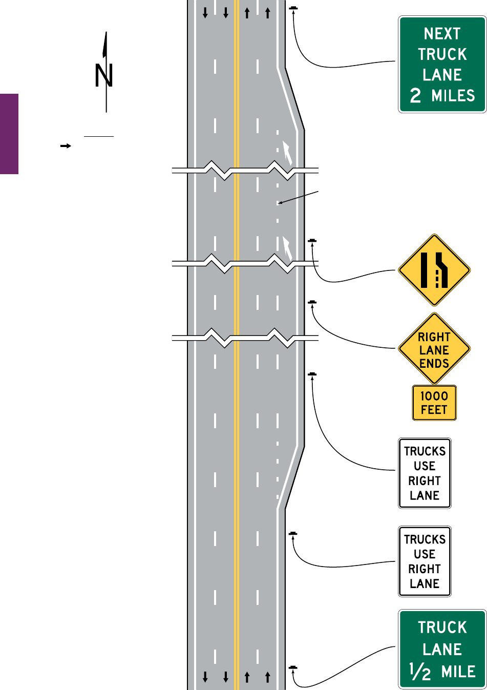
Page 264 MUTCD 11th Edition
Month 2023December 2023
Sect. 2D.53
Figure 2D-26. Example of Signing for a Truck Lane
D17-1
W4-2R
W9-1
(optional)
W16-2P
(optional)
R4-5
R4-5
D17-2
Legend
Direction of travel
Notes:
1. See Chapter 2B for
regulatory signs
2. See Chapter 2C for
warning signs
3. See Chapter 3B for
pavement markings
Optional dotted
lane line
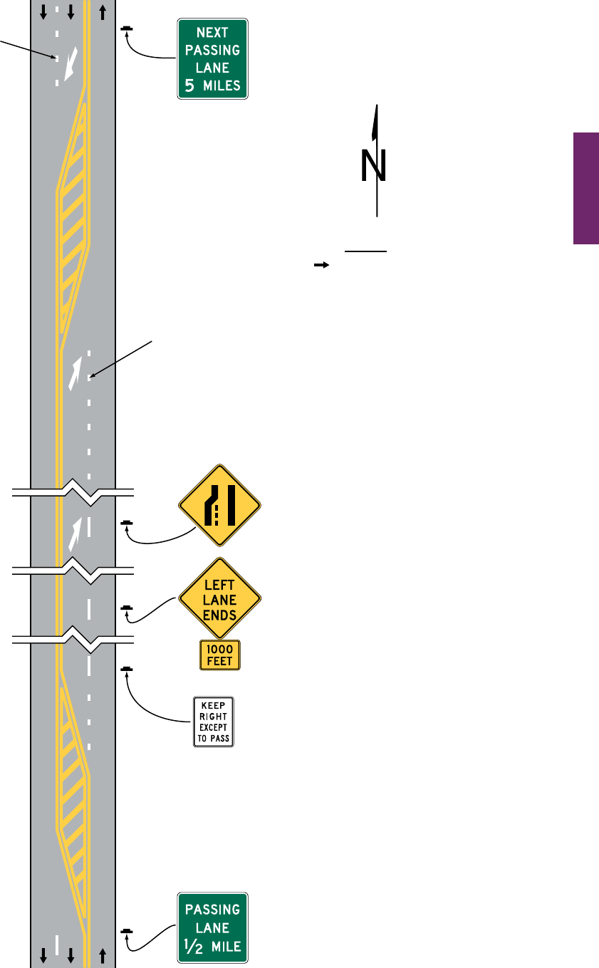
MUTCD 11th Edition Page 265
Month 2023December 2023
Sect. 2D.53
Figure 2D-27. Example of Signing for an Intermittent Passing Lane
W4-2L
W9-1L
(optional)
Optional dotted
lane line
W16-2P
(optional)
R4-16
D17-4
D17-3
Notes:
1. See Chapter 2B for regulatory signs
2. See Chapter 2C for warning signs
3. See Chapter 3B for pavement markings
Legend
Direction of travel
Optional dotted
lane line
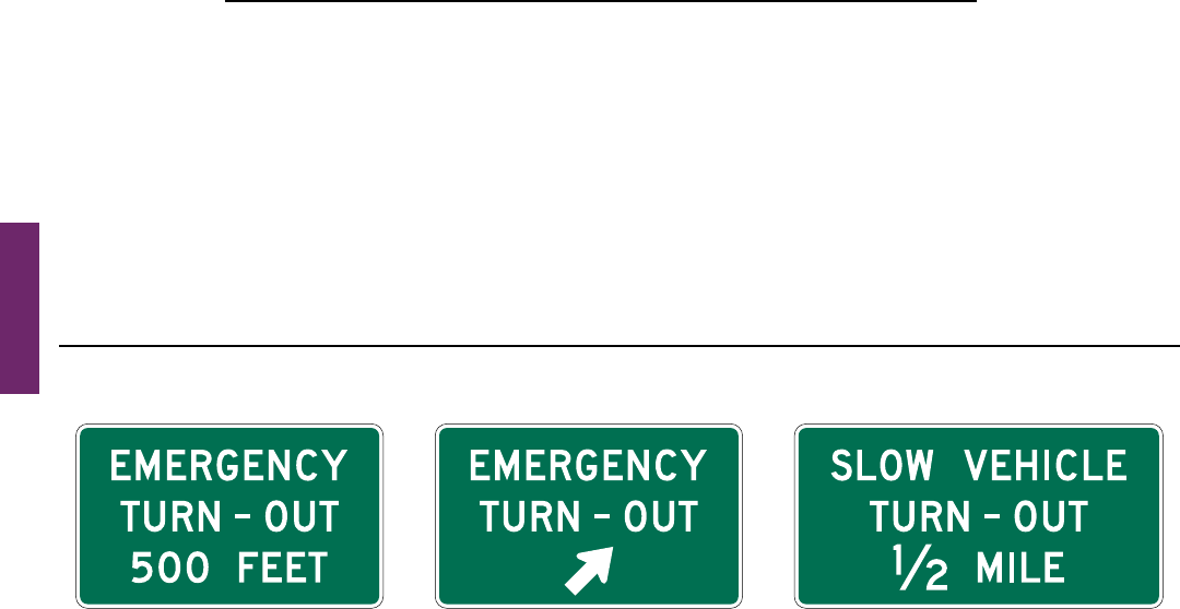
Page 266 MUTCD 11th Edition
Month 2023December 2023
Sect. 2D.54
Section 2D.54 Emergency and Slow Vehicle Turn-Out Signs (D17-5 through D17-7)
Guidance:
01 If an emergency turn-out area has been provided where a shoulder is not available for emergency stopping
or where there is part-time shoulder use by trafc (see Section 2G.23), Emergency Turn-Out signs should be
installed. The Advance Emergency Turn-Out Advance (D17-5) sign (see Figure 2D-28) should be installed
between ¼ mile and 500 feet in advance of the turn-out area. The Emergency Turn-Out Directional (D17-6)
sign (see Figure 2D-28) should be installed near the beginning of the turn-out area.
02 If a slow vehicle turn-out area has been provided for slow-moving trafc, an Advance Slow Vehicle Turn-Out
(D17-7) sign (see Figure 2D-28) should be installed in advance of the turn-out area.
Support:
03 Anexampleofsigningforanemergencyturn-outisshowninFigure 2D-29.
04 Section2B.42containsinformationregardingregulatorysignsforslowvehicleturn-outareas.
Figure 2D-28. Emergency and Slow Vehicle Turn-Out Signs
D17-5 D17-6 D17-7
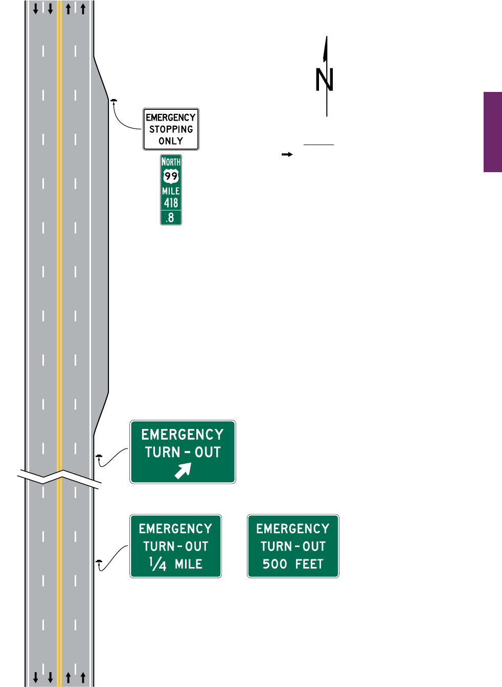
MUTCD 11th Edition Page 267
Month 2023December 2023
Sect. 2D.54
Figure 2D-29. Example of Signing for an Emergency Turn-Out
R8-7
D10-5
D17-5 D17-5
OR
Legend
Direction of travel
D17-6
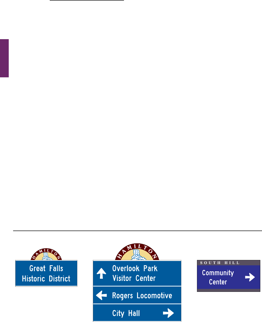
Page 268 MUTCD 11th Edition
Month 2023December 2023
Sect. 2D.55
OTHER GUIDE SIGNS
Section 2D.55 Community Waynding Signs
Support:
01 Communitywayndingguidesignsarepartofacoordinatedandcontinuoussystemofsignsthatdirect
touristsandotherroaduserstokeycivic,cultural,visitor,andrecreationalattractionsandothersimilarsecondary
destinations within a city or a local urbanized or downtown area.
02 Communitywayndingguidesignsareatypeofdestinationguidesignforconventionalroadswithacommon
colorand/oridenticationmarkerfordestinationswithinanoverallwayndingguidesignplanforanarea.
03 Figures 2D-30 through 2D-32illustratevariousexamplesofthedesignandapplicationofcommunity
wayndingguidesigns.
Standard:
04 The use of community waynding guide signs shall be limited to conventional roads. Community
waynding guide signs shall not be installed on freeway or expressway mainlines or ramps. Direction
to community waynding destinations from a freeway or expressway shall be limited to the use of a
Supplemental guide sign (see Section 2E.51) on the mainline and a Destination sign (see Section 2D.36)
on the ramp to direct road users to the area or areas within which community waynding guide signs
are used. The individual waynding destinations shall not be displayed on the Supplemental guide and
Destination signs except where the destinations are in accordance with the State or agency policy on
Supplemental guide signs.
05 Community waynding guide signs shall not be used to provide direction to primary destinations or
highway routes or streets. Destination or other guide signs shall be used for this purpose as described
elsewhere in this Chapter and shall have priority over any community waynding sign in placement,
prominence, and conspicuity.
06 Because regulatory, warning, and other guide signs have a higher priority, community waynding
guide signs shall not be installed where adequate spacing cannot be provided between the community
waynding guide sign and other higher-priority signs. Community waynding guide signs shall not be
installed in a position where they would obscure the road users’ view of other trafc control devices.
07 Community waynding guide signs shall not be mounted overhead.
Guidance:
08 If used, a community waynding guide sign system should be established on a local municipal or equivalent
jurisdictional level or for an urbanized area of adjoining municipalities or equivalent that form an identiable
geographic entity that is conducive to a cohesive and continuous system of signs. Community waynding
guide signs should not be used on a regional or statewide basis where infrequent or sparse placement does not
contribute to a continuous or coordinated system of signing that is readily identiable as such to the road user.
In such cases, Destination or other guide signs detailed in this Chapter should be used to direct road users to an
identiable area in which the type of eligible destination described in Paragraph 1 of this Section is located.
09 When a system of community waynding guide signs is being considered, the system of existing guide signs
should be evaluated for applicability and general compliance with the provisions of this Manual to ensure
road user directional guidance is adequately being addressed.
Figure 2D-30. Examples of Community Wayfinding Guide Signs
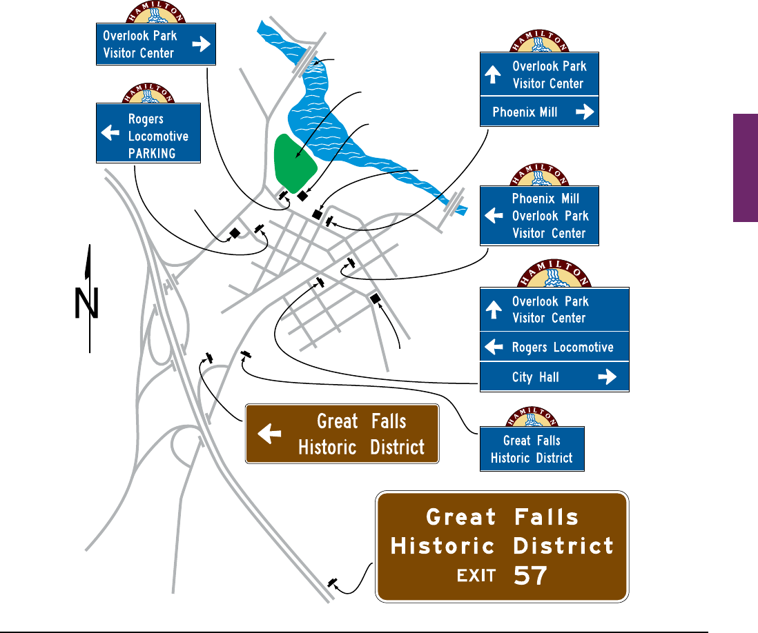
MUTCD 11th Edition Page 269
Month 2023December 2023
Support:
10 ThespecicprovisionsofthisSectionregardingthedesignofcommunitywayndingsignlegendsapply
tovehicularcommunitywayndingsignsanddonotapplytothosesignsthatareintendedonlytoprovide
informationordirectiontopedestriansorotherusersofasidewalkorroadsidearea.
Guidance:
11 Because pedestrian waynding signs typically use smaller legends that are inadequately sized for viewing by
vehicular trafc and because they can provide direction to pedestrians that might conict with that appropriate
for vehicular trafc, waynding signs designed for and intended to provide direction to pedestrians or other
users of a sidewalk or other roadside area should be located to minimize their conspicuity to vehicular trafc.
Such signs should be located as far as practicable from the street, such as at the far edge of the sidewalk. Where
locating such signs farther from the roadway is impracticable, the pedestrian waynding signs should have their
conspicuity to vehicular trafc minimized by employing one or a combination of the following methods:
A. Locating signs away from intersections where high-priority trafc control devices are present.
B. Facing the pedestrian message toward the sidewalk and away from the street.
C. Cantilevering the sign over the sidewalk if the pedestrian waynding sign is mounted at a height consistent
with vehicular trafc signs, removing the pedestrian waynding signs from the line of sight in a sequence
of vehicular signs.
Figure 2D-31. Example of a Community Wayfinding Guide Sign System
Showing Direction from a Freeway or Expressway
ROGERS
LOCOMOTIVE
OVERLOOK
PARK
VISITOR
CENTER
PHOENIX
MILL
CITY
HALL
GREAT FALLS
DESTINATION GUIDE SIGN
SUPPLEMENTAL GUIDE SIGN
Sect. 2D.55

Page 270 MUTCD 11th Edition
Month 2023December 2023
Sect. 2D.55
12 To further minimize their conspicuity to vehicular trafc during nighttime conditions, pedestrian waynding
signs should not be retroreective.
Support:
13 Colorcodingissometimesusedoncommunitywayndingguidesignstohelproadusersdistinguishbetween
multiplepotentiallyconfusingtrafcgeneratordestinationslocatedindifferentneighborhoodsorsubareaswithin
acommunityorarea.
Option:
14 Attheboundariesofthegeographicalareawithinwhichcommunitywayndingguidesigningisused,an
informationalguidesignmaybepostedtoinformroadusersaboutthepresenceofwayndingsigningandto
identifythemeaningsofthevariouscolorcodesorpictographsthatarebeingused.
Standard:
15 These informational guide signs shall have a white legend and border on a green background and
shall have a design similar to that illustrated in Figure 2D-1 and shall be consistent with the basic design
principles for guide signs. These informational guide signs shall not be installed on freeway or expressway
mainlines or ramps.
16 The color coding or a pictograph of the identication markers of the community waynding guide
signing system shall be included on the informational guide sign posted at the boundary of the community
waynding guide signing area. The color coding or pictographs shall apply to a specic, identiable
neighborhood or geographical subarea within the overall area covered by the community waynding guide
signing. Color coding or pictographs shall not be used to distinguish between different types of destinations
that are within the same designated neighborhood or subarea. The color coding shall be accomplished
by the use of different colored square or rectangular panels on the face of the informational guide sign,
each positioned to the left of the neighborhood or named geographic area to which the color-coding panel
applies. The height of the colored square or rectangular panels shall not exceed 2 times the height of the
upper-case letters of the principal legend on the sign.
Figure 2D-32. Example of a Color-Coded Community Wayfinding Guide Sign System
STEWART
PARK
VISITOR
CENTER
ART MUSEUM
COLLEGETOWN
LAKEFRONT
PERFORMING
ARTS CENTER
GENERAL INFORMATION
SIGN (see Section 2H.05)
RENWICK
CORPORATE BOUNDARY
CLINTON
HOUSE
PARKING
DOWNTOWN
COMMUNITY
CENTER
SOUTH HILL
DESTINATION GUIDE SIGN
DESTINATION GUIDE SIGN

MUTCD 11th Edition Page 271
Month 2023December 2023
Option:
17
Thedifferentcoloredsquareorrectangularpanelsmayincludeeitherablackorawhite(whicheverprovidesthe
bettercontrastwiththecolorofthepanel)letter,numeral,orotherappropriatedesignationtoidentifythedestination.
18
Exceptfortheinformationalguidesignpostedattheboundaryofthewayndingguidesignarea,community
wayndingguidesignsmayusebackgroundcolorsotherthangreeninordertoprovideacoloridenticationfor
thewayndingdestinationsbygeographicalareawithintheoverallwayndingguidesigningsystem.Color-coded
communitywayndingguidesignsmaybeusedwithorwithouttheboundaryinformationalguidesigndisplaying
corresponding color-coding panels described in Paragraphs 13 through 16 of this Section. Except as provided in
Paragraph19ofthisSection,inadditiontothecolorsthatareapprovedinthisManualforuseonofcialtrafc
controlsigns(seeSection2A.06),otherbackgroundcolorsmayalsobeusedforthecolorcodingofcommunity
wayndingguidesigns.
Standard:
19 The standard colors of red, orange, yellow, purple, or the uorescent versions thereof, uorescent
yellow-green, and uorescent pink shall not be used as background colors for community waynding guide
signs, in order to minimize possible confusion with critical, higher-priority regulatory and warning sign
color meanings readily understood by road users.
20 The minimum contrast value of legend color to background color for community waynding guide signs
shall be at least 0.70 (or 70%).
21 All messages, borders, legends, and backgrounds of community waynding guide signs and any
identication markers shall be retroreective (see Sections 2A.21 and 2A.22).
22 Community waynding guide signs, exclusive of any identication marker used, shall be rectangular
in shape.
Guidance:
23 Simplicity and uniformity in design, position, and application as described in Section 2A.04 are important
and should be incorporated into the community waynding guide sign design and location plans for the area.
24 Community waynding guide signs should be limited to three destinations per sign (see Section 2D.06).
25 Abbreviations (see Section 1D.08) should be kept to a minimum, and should include only those that are
commonly recognized and understood.
26 Horizontal lines of a color that contrasts with the sign background color should be used to separate groups
of destinations by direction from each other.
Support:
27 Thebasicrequirementforallhighwaysigns,includingcommunitywayndingsigns,isthattheybelegible
tothoseforwhomtheyareintendedandthattheybeunderstandableintimetopermitaproperresponse.Section
2A.04containsadditionalinformationonthedesignofsigns,includingdesirableattributesofeffectivedesigns.
Guidance:
28 Word messages should be as brief as practical and the lettering should be large enough to provide the
necessary legibility distance.
Standard:
29 The minimum specic ratio of letter height to legibility distance shall comply with the provisions of
Section 2A.08. The size of lettering used for destination and directional legends on community waynding
signs shall comply with the provisions of minimum letter heights as provided in Section 2D.05.
30 Interline and edge spacing shall comply with the provisions of Section 2D.05.
31 Except as provided in Paragraph 34 of this Section, the lettering style used for destination and
directional legends on community waynding guide signs shall comply with the provisions of Section 2D.04.
32 The lettering for destinations on community waynding guide signs shall be a combination of lower-case
letters with initial upper-case letters (see Section 2D.04). All other word messages on community waynding
guide signs shall be in all upper-case letters.
Guidance:
33 Except as provided in Paragraphs 34 and 35 of this Section, letters, numerals, and other characters should be
composed of the Standard Alphabets as detailed in the “Standard Highway Signs” publication (see Section 1C.05).
Option:
34 AletteringstyleotherthantheStandardAlphabetsprovidedinthe“StandardHighwaySigns”publication
(seeSection1C.05)maybeusedoncommunitywayndingguidesignsifanengineeringstudydeterminesthatthe
legibilityandrecognitionvaluesforthechosenletteringstylemeetorexceedthevaluesfortheStandardAlphabets
forthesamelegendheightandstrokewidth.
Sect. 2D.55

Page 272 MUTCD 11th Edition
Month 2023December 2023
Standard:
35 If a lettering style other than the Standard Alphabets is used, the alternative lettering style shall be
conventional in form. The letters, numerals, and other characters shall not be italic, oblique, script, highly
decorative, or of other unusual forms.
36 In accordance with Section 2A.04, except for signs that are designed and located with the intent to be
viewed only by pedestrians, bicyclists stopped out of the ow of trafc, or occupants of parked vehicles,
Internet and e-mail addresses, including domain names and uniform resource locators (URL), and
scanning graphics for the purpose of obtaining information (see Section 2A.04), shall not be displayed on
any community waynding guide sign or sign assembly.
37 The arrow location and priority order of destinations shall follow the provisions described in Sections
2D.08 and 2D.36. Arrows shall be of the designs provided in Section 2D.08.
Option:
38 Pictographs(seedenitioninSection1C.02)maybeusedoncommunitywayndingguidesigns.
Standard:
39 If a pictograph is used, its height shall not exceed 2 times the height of the upper-case letters of the
principal legend on the sign.
40 Except for pictographs, symbols that are not approved in this Manual for use on guide signs shall not be
used on community waynding guide signs.
41 Business logos, commercial graphics, or other forms of advertising (see Section 1D.07) shall not be used
on community waynding guide signs or sign assemblies.
Option:
42 Othergraphicsthatspecicallyidentifythewayndingsystem,includingidenticationmarkers,maybeused
ontheoverallsignassemblyandsignsupports.
Support:
43 Anidenticationmarkerconsistsofashape,color,and/orpictographthatisusedasavisualidentierforthe
communitywayndingguidesigningsystemforanarea.Figure2D-30showsexamplesofidenticationmarker
designsthatcanbeusedwithcommunitywayndingguidesigns.
Option:
44 Anidenticationmarkermaybeusedinacommunitywayndingguidesignassembly,ormaybeincorporated
intotheoveralldesignofacommunitywayndingguidesign,asameansofvisuallyidentifyingthesignaspartof
anoverallsystemofcommunitywayndingsignsanddestinations.
Standard:
45 The sizes and shapes of identication markers shall be smaller than the community waynding guide
signs themselves. Identication markers shall not be designed to have an appearance that could be mistaken
by road users as being a trafc control device.
Guidance:
46 The area of the identication marker should not exceed ¹⁄
5
of the area of the community waynding guide sign
with which it is mounted in the same sign assembly.
Section 2D.56 Signing of Named Highways for Mapping and Address Purposes
Support:
01 Ahighwaynameistheofciallydesignatednameofafreeway,expressway,orconventionalroadfor
navigational,ofcialmapping,andaddresspurposes.Somehighwaysarenamedinadditiontoorinlieuofbeing
assignedahighwayroutenumber.Memorial,honorary,ceremonial,orothersecondarynames,suchastouring
routeandbywaynames,arenotconsideredtobehighwaynames.
Option:
02 Guidesignsmaycontainstreetorhighwaynamesifthepurposeistoenhancedrivercommunicationand
guidance;however,theyaretobeconsideredassupplementalinformationtoroutenumbers.
Standard:
03 Highway names shall not replace ofcial numeral designations.
04 Memorial, honorary, or other secondary names (see Section 2M.10) shall not appear on supplemental
signs or on any other information sign on or along the highway or its intersecting routes.
05 The use of route signs shall be restricted to signs ofcially used for guidance of trafc in accordance
with this Manual and the “Purpose and Policy” statement of the American Association of State Highway
and Transportation Ofcials that applies to Interstate and U.S. numbered routes.
Sect. 2D.55 to 2D.56
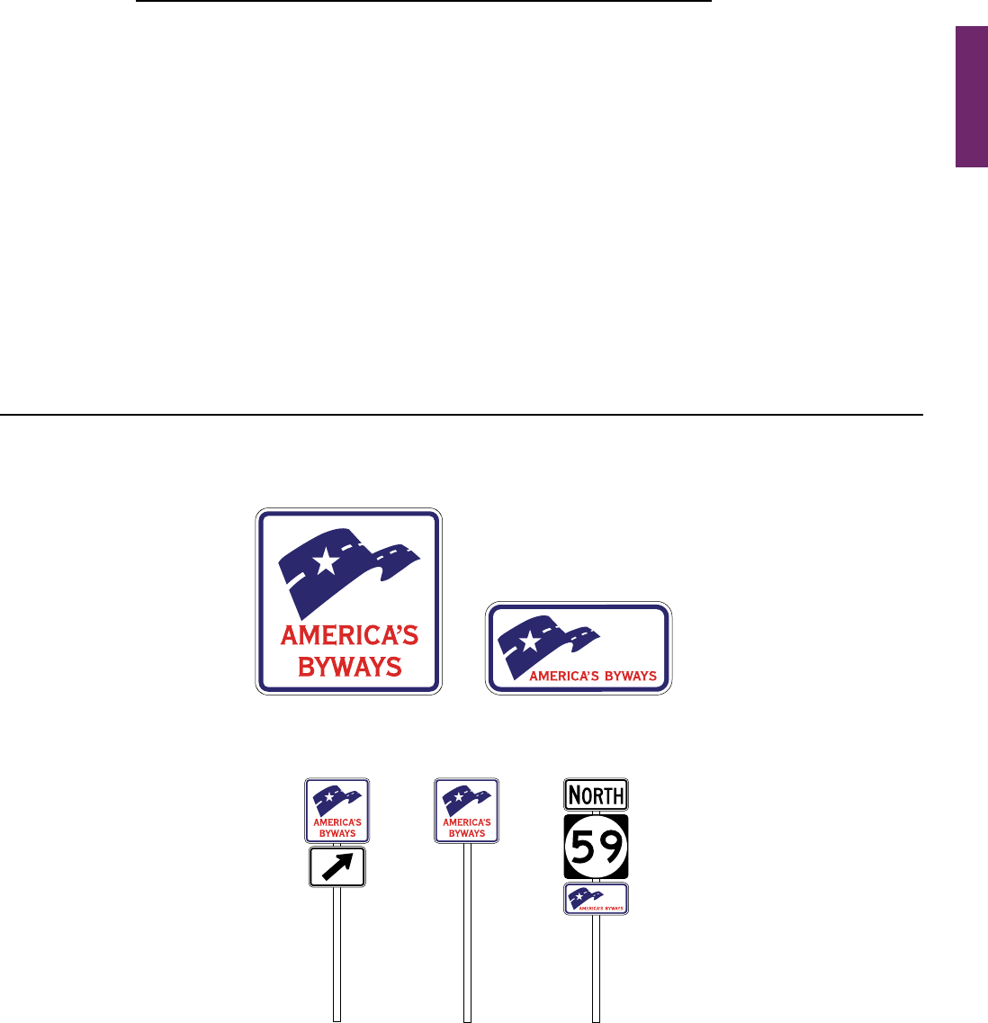
MUTCD 11th Edition Page 273
Month 2023December 2023
Option:
06 Unnumberedrouteshavingmajorimportancetoproperguidanceoftrafcmaybesignedifcarriedoutin
accordancewiththeaforementionedpolicies.Forunnumberedhighways,anametoenhancerouteguidance
maybeusedwherethenameisappliedconsistentlythroughoutitslength.
Guidance:
07 Only one name should be used to identify any highway, whether numbered or unnumbered.
Section 2D.57 National Scenic Byways Sign and Plaque (M10-1 and M10-1aP)
Support:
01 Certain roads have been designated by the U.S. Secretary of Transportation as National Scenic Byways or
All-AmericanRoadsbasedontheirarcheological,cultural,historic,natural,recreational,orscenicqualities.
Option:
02 StateandlocalhighwayagenciesmayinstalltheNationalScenicByways(M10-1)signor(M10-1aP)plaque
(see Figure 2D-33) at entrance points to a route that has been recognized by the U.S. Secretary of Transportation as
aNationalScenicBywayoranAll-AmericanRoad.TheM10-1signmaybeinstalledasindependentDirectional
(seeSection2D.32)orConrming(seeSection2D.33)assembliesatperiodicintervalsalongthedesignatedroute
andnearintersectionswherethedesignatedrouteturnsorfollowsadifferentnumberedhighway.TheM10-1aP
plaquemaybeinstalledbelowaroutesigninaConrmingassembly.Atlocationswhereroadsidefeatureshave
beendevelopedtoenhancethetraveler’sexperiencesuchasrestareas,historicsites,interpretivefacilities,or
scenicoverlooks,theNationalScenicBywayssignorplaquemaybeplacedontheassociatedsignassemblyto
informtravelersthatthesitecontributestothebywaytravelexperience.
Guidance:
03 Where the byway is identied only by the National Scenic Byways sign, the Directional assembly should
consist of the M10-1 sign and an M5 series or M6 series auxiliary plaque when indication of a turn is necessary
to remain on the byway route.
Figure 2D-33. National Scenic Byways Sign and Plaque, and Examples of Use
M10-1 M10-1aP
A – National Scenic Byways sign and plaque
B – Examples of use of the National Scenic Byways sign and plaque
Confirming
assembly
Independent
Confirming
assembly
Independent
Directional
assembly
Sect. 2D.56 to 2D.57

Page 274 MUTCD 11th Edition
Month 2023December 2023
04 Where the name of the byway is to be displayed on identication signs or plaques along the byway route, the
name should be displayed in a Directional or Conrming assembly as follows (see Figure 2D-34):
A. On a Byway Identication (M10-2aP) plaque (see Section 2D.58) mounted below the M10-1 sign; or
B. On a Byway Identication (M10-2) sign (see Section 2D.58) with the M10-1aP plaque mounted below the sign.
05 In either case, the size of the National Scenic Byways (M10-1) sign, (M10-1aP) plaque, Byway Identication
(M10-2) sign, and Byway Identication (M10-2aP) plaque should be consistent with that specied for route signs
(see Section 2D.10) for the roadway classication.
06 Where the name of the byway is to be displayed along the byway route as provided in Paragraph 4 of this
Section, the byway Directional or Conrming assemblies should be located separately from any Route Sign
assemblies or Destination guide signs.
Standard:
07 When a National Scenic Byways sign is installed on a National Scenic Byway or an All-American Road,
the design shown for the M10-1 sign or M10-1aP plaque in Figure 2D-33 shall be used. Use of this design
shall be limited to routes that have been designated as a National Scenic Byway or All-American Road by
the U.S. Secretary of Transportation.
08 If used, the M10-1 sign or M10-1aP plaque shall be placed such that the highway route signs have
primary visibility for the road user.
09 The M10-1 sign or the M10-1aP plaque shall not be installed as sign panels on a guide sign or as part of
a guide sign assembly.
Section 2D.58 State-Designated Scenic Byway, Historic Trail, and Auto Tour Route Signs
Support:
01 SigningforState-designatedscenicbyways,historictrails,andautotourroutes,issimilarinconcepttothatfor
National Scenic Byways as provided in Section 2D.57.
02 Namedhighwaysareofciallydesignatedandshownonofcialmapsandservethepurposeofproviding
routeguidance,primarilyonunnumberedhighways,andpropertyaddresses.Ahighwaydesignatedasatrail,
autotourroute,orbywayisnotconsideredtobeahighwaynameforthepurposesofhighwaysigningorroaduser
navigationandorientation.Section2D.56containsprovisionsforthesigningofnamedhighways.
03 Section1D.09providesinformationontheauthorityforplacementoftrafccontroldeviceswithinthe
highway right-of-way.
Guidance:
04 Route Sign assemblies and Destination guide signs should have priority in visibility and location over signing
related to historic trails, auto tour routes, and byways.
Option:
05 IdenticationsignsforaStatescenicbywaymaybeinstalledalongconventionalroadsthathavebeen
designatedaspartofaStatescenicbywaysystem.ABywayIdentication(M10-2)sign(seeFigure 2D-34) with
thenameofthebywaydisplayedmaybeinstalledinaDirectionalorConrmingassemblywiththeSCENIC
BYWAY (M10-3bP) plaque (see Figure 2D-34)mountedbelowtheM10-2sign.
06 WhereaNationalScenicBywayispartofaStatescenicbywaysystem,theNationalScenicByways
(M10-1aP)plaque(seeSection2D.57)maybeinstalledinaDirectionalorConrmingassemblybelowthe
BywayIdentication(M10-2)signorStateScenicByway(M10-3orM10-3a)sign(seeFigure 2D-34) for the
State scenic byway.
07 AStateScenicBywaySystem(M10-3)signmaybeinstalledinaDirectionalorConrmingassemblywith
thenameofthebywaydisplayedonaBywayIdentication(M10-2aP)plaquebelowthesign(seeFigure 2D-34).
08 AStateScenicByway(M10-3a)signwithasimplegraphicandthenameofthebywaydisplayedmaybe
installedinaDirectionalorConrmingassemblywiththeSCENICBYWAY(M10-3bP)plaquemountedbelow
the M10-3a sign.
09 Identicationsignsforahistorictrail,suchastheNationalHistoricTrailsadministeredbytheNational
ParkService,maybeinstalledalongsegmentsofconventionalroadsthatcoincidewiththeoriginalrouteofthe
trail.NationalHistoricTrailIdentication(M11-1)signs(seeFigure 2D-34)maybeinstalledinaDirectional
orConrmingassemblywithaHISTORICROUTE(M11-1aP),CROSSING(M11-1bP),orAUTOTOUR
ROUTE (M11-1cP) auxiliary plaque (see Figure 2D-34)mountedbelowtheM11-1sign.Thebeginningandend
ofahistorictrailrouteorautotourroutemaybeindicatedwithaBEGIN(M4-14P)orEND(M4-6P)auxiliary
plaque (see Figure 2D-5)withawhitelegendandborderonabrownbackgroundmountedabovethehistorictrail
identicationsign.ThelengthoftheroutemaybeidentiedbyaNEXTXXMILES(M11-1dP)auxiliaryplaque
mountedbelowtheM11-1aPorM11-1cPauxiliaryplaque.
Sect. 2D.57 to 2D.58
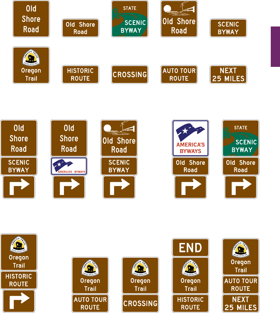
MUTCD 11th Edition Page 275
Month 2023December 2023
Sect. 2D.58
Figure 2D-34. Byway Identification, State Scenic Byway, and
National Historic Trail Signs and Plaques, and Examples of Use
C – Examples of Directional and Confirming assemblies for National Historic Trails
Independent Confirming assembliesIndependent
Directional
assembly
State Scenic
Byway
State Scenic Byway
that is also designated as
a National Scenic Byway
State Scenic
Byway
B – Examples of Directional assemblies for National and State Scenic Byways
Byway identification emphasized Byway system emphasized
A – Byway Identification, State Scenic Byway, and National Historic Trails signs and plaques
M10-3bP
M10-3
M10-2
M11-1 M11-1aP M11-1bP M11-1cP M11-1dP
M10-2aP
National Scenic
Byway system
State Scenic
Byway system
M10-3a

Page 276 MUTCD 11th Edition
Month 2023December 2023
Sect. 2D.58
Guidance:
10 The design and size of historic trail and State scenic byway identication or system signs should comply with
the general provisions and principles for route signs (see Section 2D.10). Designs should be simple, dignied,
and devoid of complex graphics. The size of the signs should not exceed the size of the route signs used along a
particular route.
Standard:
11 Scenic byway, historic trail, and auto tour route sign designs shall not have a similar design to or
resemble a highway route sign
Guidance:
12 Where used, historic trail and State scenic byway identication signs should be installed as Directional
(see Section 2D.32) or Conrming (see Section 2D.33) assemblies at independent locations, separate from other
Route Sign assemblies and Destination guide signs. Where used, Conrming assemblies for the trail or byway
should be installed at less frequent intervals than Conrming assemblies for the numbered route.
Support:
13 Where all or part of the original route of a historic trail does not follow a roadway, an auto tour route is
sometimesestablishedalongaconventionalroadinthegeneralvicinityofthehistoricalrouteofthetrail.
ExamplesincludeautotourroutesfollowingotherroutesthatparalleltheoriginalroutesoftheLewisandClark
NationalHistoricTrail,theOregonNationalHistoricTrail,andtheSantaFeNationalHistoricTrail. The auto
tourrouteisshownontouringmapsalongStateorotherhighwaysandprovidesaccesstositesonthetrailfrom
those highways.
14 Asystemofsigningprovidingdirectionalongconventionalroadsforahistorictrailwithanautotourrouteis
shown in Figure 2D-35.ExamplesofDestinationandSupplementalguidesignsprovidingdirectiontohistorictrail
sitesfromafreewayorexpresswayinterchangeareshowninFigure 2D-36.
Guidance:
15 Signing for historic trails should be limited to Destination signs for the sites related to the trail and to
Directional and Conrming assemblies for the original portions of the trail itself. If an auto tour route has been
designated along other highways to provide access to sites along the original trail as described in Paragraph 13
of this Section, then the signing should be limited to Destination signs for those sites and directional signing to
access the original route of the trail. Identication signs for the auto tour route should not be installed. Instead,
direction along the auto tour route should rely on the touring map and other directional signs for the highways
that the auto tour route follows.
Standard:
16 Identication signs for historic trails, auto tour routes, and scenic byways shall not be installed on
freeways or expressways, except as necessary to provide continuity between discontinuous segments of
conventional roadways that are designated as a trail, auto tour route, or byway, for which the freeway or
expressway provides the only connection between the segments. If installed on freeways or expressways, the
identication signs shall be installed as independent trailblazer assemblies (see Sections 2D.34 and 2E.55)
and shall not be installed with other route signs or Conrming assemblies or on guide signs. If installed on
freeways or expressways, the trailblazer assemblies for the trail, auto tour route, or byway shall be installed
at less frequent intervals than Conrming assemblies for the highway route.
17 Identication signs for historic trails, auto tour routes, and scenic byways shall not be installed as sign
panels on a guide sign or as part of a guide sign assembly.
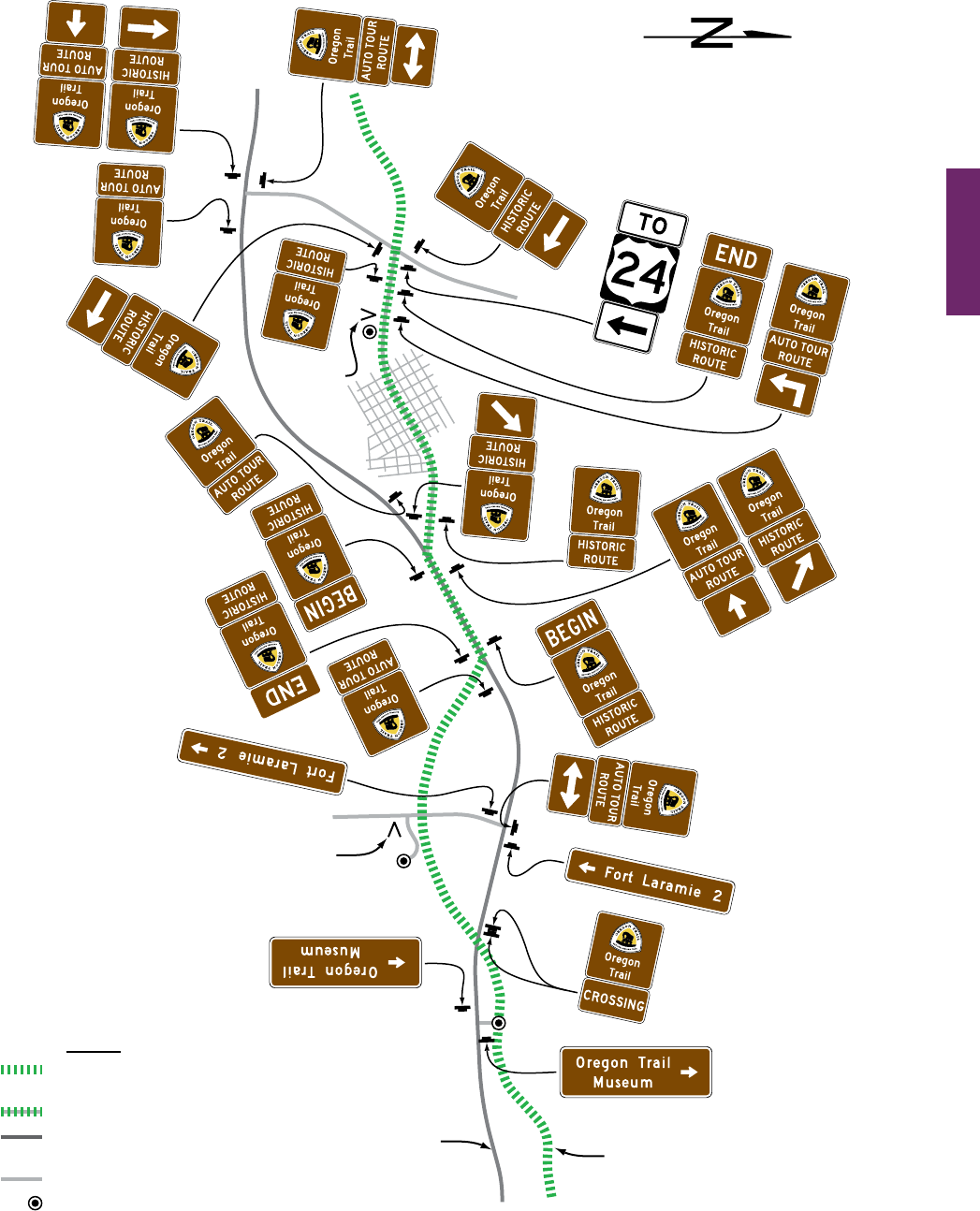
MUTCD 11th Edition Page 277
Month 2023December 2023
Sect. 2D.58
Figure 2D-35. Example of Guide and Directional Signing for a National Historic Trail
Site
Identification
Sign
Site
Identification
Sign
Auto Tour
Route
Historic
Trail
Fort
Laramie
Museum
U
.
S
.
2
4
U
.
S
.
2
4
U
.S
.
2
4
Legend
Historic Trail
(Original Alignment)
Historic Trail on Roadway
Designated Auto
Tour Route
Other Roads
Trail-Related Site
or Trail Access

Page 278 MUTCD 11th Edition
Month 2023December 2023
Sect. 2D.58
Figure 2D-36. Example of Historic Trails Signing from an Expressway or Freeway
Exit directions
guide sign
Supplemental
guide sign
Advance
guide sign
OR
OR
Destination guide sign
OR
OR

MUTCD 11th Edition Page 279
Month 2023December 2023
Sect. 2D.59
Section 2D.59 Emergency Routing Signs and Plaques (M4-11 and M4-12 Series)
Support:
01 Aspartofanagency’stransportationincidentmanagementplanitissometimesdesirabletopermanentlysign
routesthatprovidereroutingoftrafcaroundhighwaysegmentssusceptibletotrafcincidents.Permanently-
installedEmergencyRoutingsignsandplaques(seeFigure2D-37)providedirectiononconventionalroadsfrom
anexitlocatedupstreamofanareathatcanbesusceptibletotrafcincidentsbacktotheoriginalrouteatapoint
downstreamoftheincident-susceptible area.
Option:
02 EMERGENCY ROUTE (M4-11 and M4-11a) signs and EMERGENCY ROUTE TO (M4-11bP and M4-11cP)
plaquesmountedonadirectionalassemblymaybepermanentlyinstalledonconventionalroadwaystoprovide
trailblazingalongadesignateddiversionaryroutetobypassatrafcincident.
Support:
03 ThepurposeofEmergencyRoutingsignsandplaquesisforcorridormanagementalongroutesthathave
recurringincidentsandhavereasonablereroutingpathsavailable.Thesesignsareintendedtobepermanently
installedtoprovideinstantreroutingguidancetoroaduserswhentrafccongestionorbackupsrstbegineven
beforeemergencyresponderscouldprovidetemporarytrafccontrolforreroutingtrafc.Thesesignscanbe
usedasastand-alonesystemorbeapartofalargersystemwhichmightalsoincorporateotherdevicessuchas
changeablemessagesigns.Thesesignsprovideroadusersassurancethatadiversionaryroutewillleadthemback
to their original route of travel.
Standard:
04 Emergency Routing signs and plaques shall only be installed at departure points and along diversion
routes for directing road users around highway segments in areas that are more susceptible to trafc
incidents (see Figure 2D-38). EMERGENCY ROUTE and EMERGENCY ROUTE TO signs shall be placed
at each turning decision point along the designated route until it rejoins the original route or until other
directional signs leading back to the original route are provided.
05 Emergency Routing signs shall have a white legend and border on a green background.
Option:
06 ForadditionalemphasisthelegendEMERGENCYROUTEorEMERGENCYROUTETOmaybedisplayed
in a yellow panel with black letters near the top of the sign (see Figure 2D-37).
Standard:
07 Orange or pink shall not be used as alternate colors on permanently-installed signs or plaques for
rerouting trafc during an incident or other event. If a route shield is displayed as part of the message,
the wording of the sign or plaque shall be EMERGENCY ROUTE TO as shown in Figure 2D -37.
Option:
08
An EMERGENCY ROUTE TO plaque with either a white legend and border on a green background (M4-11bP)
orblacklegendandborderonayellowbackground(M4-11cP)maybeaddedtothetopofaconventionalRoute
assemblyonadiversionroutetoprovidedirectionbacktotheoriginalroutedownstreamoftheincident
(see Figures 2D-37 and 2D-38).
09 Acombinationwarningandregulatorymessagesignwithashingbeaconsmountedaboveandthelegend,
WHENFLASHING[ROUTE]CLOSEDAHEAD/USEEMERGENCYROUTE[NEXTRIGHTorEXITXX]
maybeusedinadvanceoftheemergencyrouteentrancetoinformroadusersoftheclosureandrequireexitingthe
primaryrouteanduseoftheemergencyroute(seeFigures 2D-37 and 2D-38).
10 TheEndEmergencyRoute(M4-12)signmaybeuseatapointalongtheemergencyroute justpriorto
thejunctionwheretrafcistoreentertheprimaryroutepasttheclosedsectionofroadway(seeFigure 2D-37
and 2D-38).
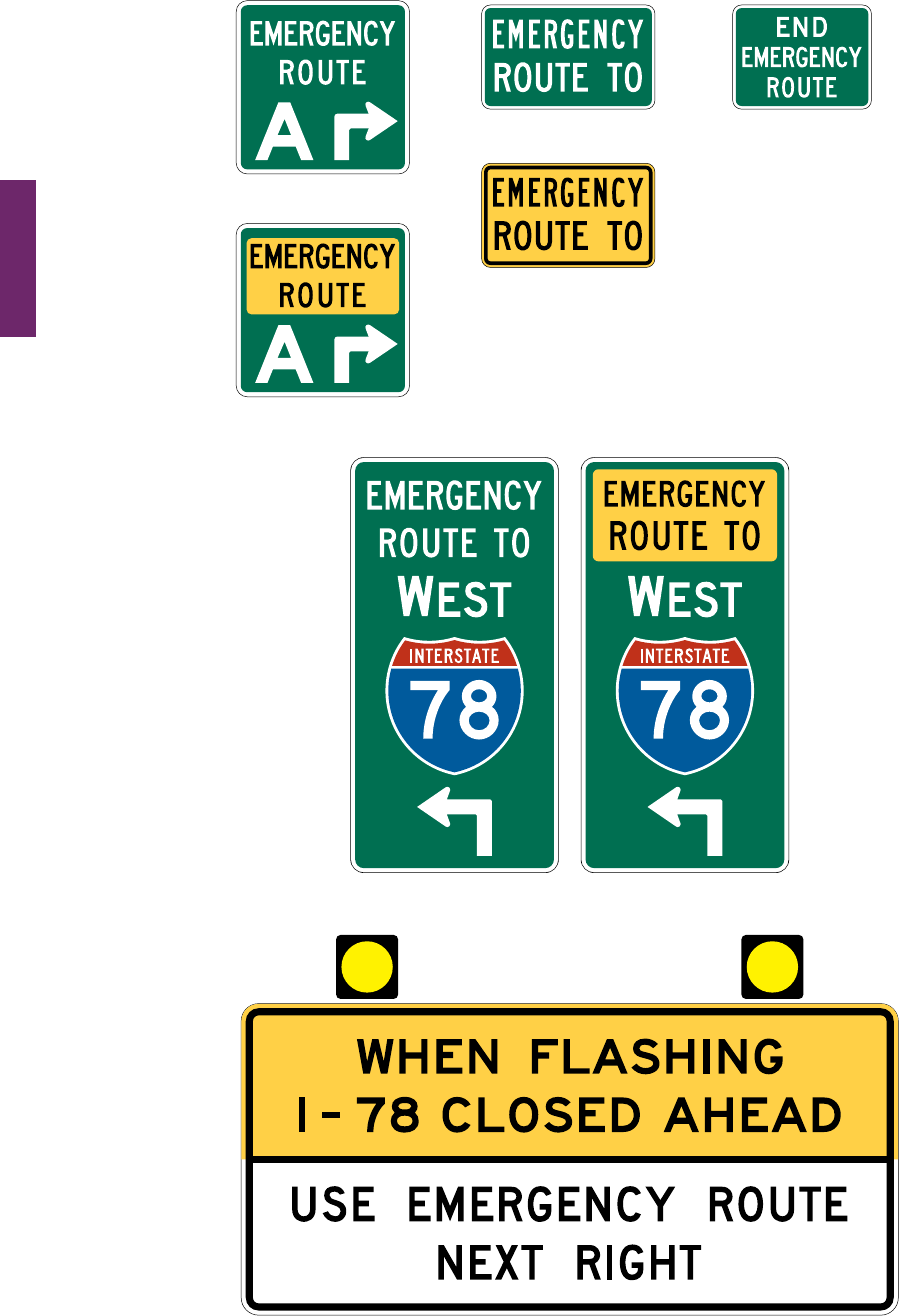
Page 280 MUTCD 11th Edition
Month 2023December 2023
Sect. 2D.59
Figure 2D-37. Signs and Plaques for Rerouting Because of Traffic Incidents
Examples of guide signs for rerouting
Example of advance sign for rerouting
M4-11
M4-11a
M4-11bP
M4-11cP
M4-12
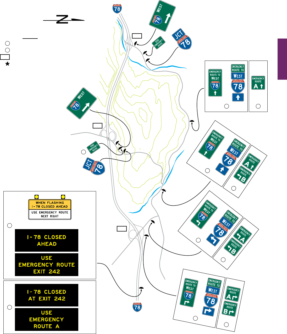
MUTCD 11th Edition Page 281
Month 2023December 2023
Sect. 2D.59
O
l
d
C
a
n
y
o
n
H
w
y
O
l
d
C
a
n
y
o
n
H
w
y
S
ky
l
i
n
e
D
r
M
ou
n
tai
n
si
d
e
A
v
e
Figure 2D-38. Example of Permanent Guide Signing for
Rerouting Because of Traffic Incidents
*
*
*
1
1
2
2
2
OR
CMS
Phase
1
CMS
Phase
2
CMS
Phase
1
CMS
Phase
2
OR
1
2
OR
1
2
OR
1
2
OR
1
2
236
242
229
Legend
Single routing
Multiple routings
Exit number
Optional
229

Page 282 MUTCD 11th Edition
Month 2023December 2023
Sect. 2D.60
SIGNING AT AIRPORTS
Section 2D.60 Signing at Airports
Support:
01 Manyroadwayswithinairportfacilities(includingterminalcurbsideroadways)areconsideredtobe
conventionalroadsbecausetheytypicallyhavefrequentdrivewaysandat-gradeintersectionsandmighthave
pedestrianactivityalongand/oracrossthem.
02 Someairportroadwayshavefullorpartialcontrolofaccessandoperatingspeedshigherthan45mphand
thuswouldbeclassiedasfreewaysorexpresswaysforsigningpurposes(seeChapter2E).Freewayorexpressway
conditionstypicallyexistontheapproachestotheairportfromotherhighways;ontheapproachestoaccesspoints
toterminals,parking,andotherpatronfacilities;andonroadwaysthatprovideexitsfromtheairportfacilityto
connect with the local or regional highway network.
03 Roadwayswithinairportsandothersimilarly-containedroadwaynetworkswithmultipleclosely-spacedaccess
pointstomultipledestinations(suchasterminals,parkingfacilities,rentalcarfacilities,andotherairportservices)
oftenpresentchallengesfortheapplicationofguidesigning.Closely-spacedsigns,excessivesignmessaging
eitherco-locatedorinsuccession,andtheresultingexcessiveinformationalloadimposedontheroaduserare
ofparticularconcernforsuchroadways.TheTransportationResearchBoard’sAirportCooperativeResearch
ProgramReport52,“WayndingandSigningGuidelinesforAirportTerminalandLandside,” contains additional
informationontheapplicationoftrafccontroldevicestotheuniquegeometricsandroadwayenvironmentthat
are typical of airports.
04 Anexampleofmajorguidesigningon the approaches to and within an airport facility roadway network is
shown in Figure 2D-39.
Guidance:
05 If adequate sign spacing cannot be provided due to the site and roadway characteristics of an airport or
similar facility, then measures should be taken to reduce the speeds of vehicles on the roadway to provide road
users with adequate time to comprehend and respond to the sign messages. Consideration should also be given to
increasing the sign letter heights to provide greater viewing distances and decision times. Where a single terminal
serves a large number of airlines, the airline information should be displayed on separate signs that appear in
sequence to limit the number of airlines displayed on a single sign or at a single location. Changeable message
signs (see Chapter 2L) should not be used to rotate the display of airlines to an approaching road user.
Support:
06 Therearevariousmethodsthatcanbeusedtohelpreducevehiclespeeds,includingroadwaygeometric
changes,implementingtrafccalmingmeasures,andincreasedenforcement.Provisionsonsettingspeedlimits
are found in Section 2B.21.
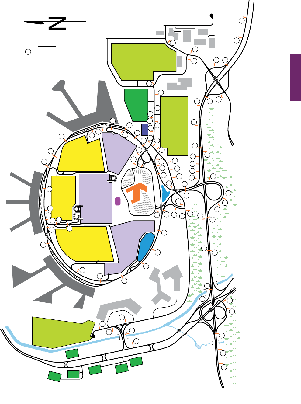
MUTCD 11th Edition Page 283
Month 2023December 2023
Sect. 2D.60
Lind
b
e
r
g
h
P
l
.
T
e
r
m
i
n
a
l
L
o
o
p
Terminal
C
Economy
Parking
Lot 4
Hourly
Parking
Term. A
Hourly
Parking
Term. C
C
B
A
Daily
Parking
Lot 2
Hotel
Daily
Parking
Lot 3
Daily
Parking
Lot 1
Hourly
Parking
Term. B
Rental
Cars
Waiting Lot
Gas
Economy
Parking
Lot 6
Terminal
B
Terminal
A
General
Aviation
Administration
Cargo
Area
Control
Tower
H
o
t
e
l
C
i
r
.
N
o
r
t
h
H
o
te
l
C
i
r
.
S
.
East Dr.
Central
Pkwy.
Metropolitan
Hwy.
U. S. 25
Earhardt Rd.
Quimby Pl.
S.
P
e
r
i
m
e
t
e
r
R
d
.
Coleman
Rd.
A
v
i
a
t
i
o
n
B
l
v
d
.
Legend
Sign number
(see Sheets 2 and 3
for sign images)
51
55
52
53
65
66
28
30
Figure 2D-39. Example of a System of Major Guide Signs
for an Airport Roadway Network (Sheet 1 of 3)
Economy
Parking
Lot 5
I-52
EXIT 162
EXIT 163
EXIT 164
To Metropolis
To Metropolis
I-52
Off-Airport Rental Cars
27
31
72
73
74
8
8
9
9
10
10
11
22
23
24
48
49
50
25
26
36
37
54
56
57
58
60
62
61
59
70
71
63
64
1
2
3
4
5
3
21
6
7
12
7
13
5
19
18
17
2
16
20
11
10
9
8
67
68
29
35
8
9
10
69
32
33
34
35
38
39
40
41
42
44
43
45
46
14
15
47
48
Notes:
1. Major guide signs are shown in this figure for illustrative purposes. Other guide signs
(such as advance signs), as well as regulatory and warning signs, have been omitted for clarity.
2. Terminal loop is a one-way clockwise roadway.
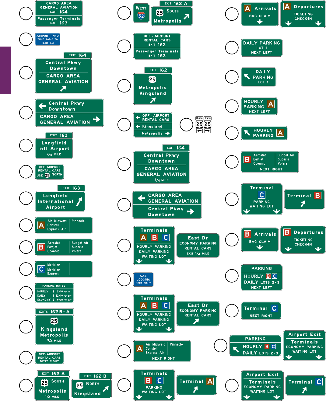
Page 284 MUTCD 11th Edition
Month 2023December 2023
Sect. 2D.60
Figure 2D-39. Example of a System of Major Guide Signs
for an Airport Roadway Network (Sheet 2 of 3)
22
23
24
8
25
26
11
10
9
38
27
33
34
30
31
32
36
35
29
28
2
5
6
7
12
14
13
15
17
3
20
19
18
16
1
4
21
37
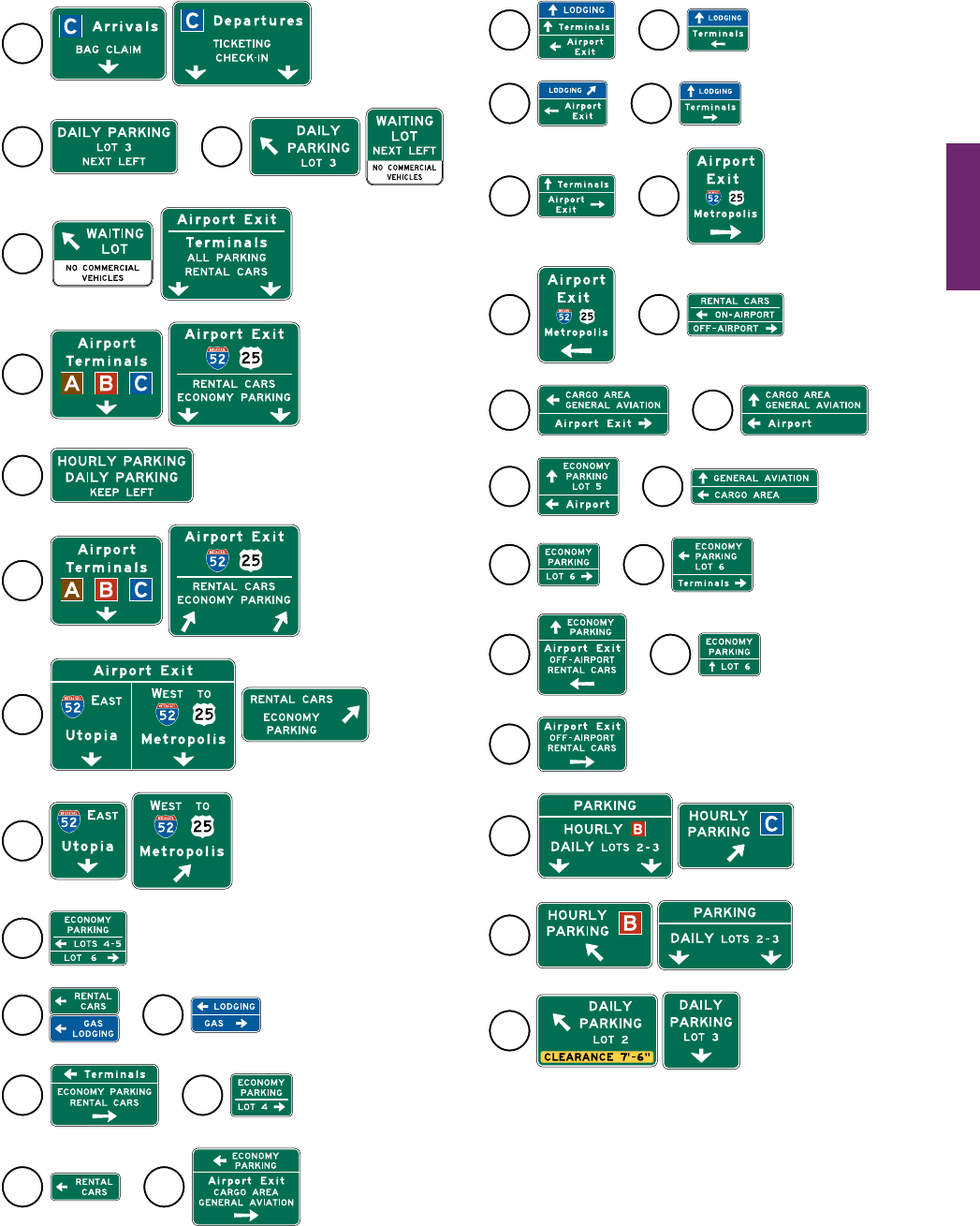
MUTCD 11th Edition Page 285
Month 2023December 2023
Sect. 2D.60
Figure 2D-39. Example of a System of Major Guide Signs
for an Airport Roadway Network (Sheet 3 of 3)
56
55
60
59
5857
71
73
72
61 62
67 68
63 64
65
66
74
47
48
49
50
51
52
53 54
44
39
43
45
46
41
40
42
70
69

December 2023
Page 286 MUTCD 11th Edition
Sect. 2D.60
(This page intentionally left blank)
